Square End Mills
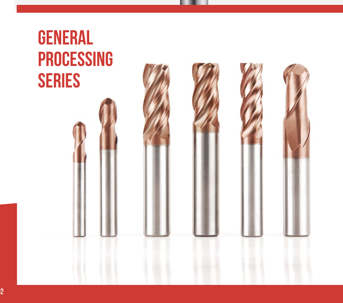
Square End Mills use a flat cutting end for operations that require a square-end geometry. Open the product page to compare available series, dimensions and catalog codes.

MSU-Manufactured Product Line
MSU manufactures solid carbide end mills for milling operations that require a defined end geometry, diameter, flute count, length and catalog coating.
Use this category to compare ten carbide end mill types, review the catalog scope, and send the workpiece and operation details needed for selection and quotation.
Send the application details once you are ready for product review.
Request an End Mill ReviewMSU’s carbide endmill range is organized by cutting-end geometry and machining task. Start with the product type, then confirm diameter, cutting length, overall length, flute count, corner or radius details, substrate or coating fields, workpiece material and machine conditions.
Square End Mills use a flat cutting end for operations that require a square-end geometry. Open the product page to compare available series, dimensions and catalog codes.
Ball Nose End Mills use a radiused cutting end for profiling and contoured toolpaths. Open the product page to compare the available series and dimensions.
Corner Radius End Mills combine a flat cutting end with a defined corner radius. Compare the available series by diameter, radius, length and application.
Micro End Mills cover the NNC, NNH, NNCH and NNX series for small-diameter applications. Confirm the exact diameter, lengths and setup requirements in the product table.
Roughing End Mills cover roughing geometries for material-removal operations. Compare the available series by diameter, workpiece, engagement and machine conditions.
T-Slot End Mills cover T-slot cutting geometry. Confirm the cutter diameter, neck or reach, slot dimensions and machine clearance on the product page.
Corner Rounding End Mills are used for defined external edge radii. Compare radius, pilot or clearance dimensions, cutter diameter and shank details.
Chamfer Mills cover the available 90-degree chamfer range. Confirm the required angle, diameter, feature and reach before choosing a catalog code.
Tapered Ball Nose End Mills combine a tapered body with a ball-end profile. Confirm the ball end, taper definition, length and toolpath requirements.
Single-Flute End Mills use a one-flute cutting geometry. Confirm the diameter, cutting length, workpiece and operating conditions on the product page.
Compare the ten end mill types side by side before choosing the next product page.
Compare End Mill TypesProduct type establishes the cutting-end geometry; it does not by itself confirm the complete tool. Use the table to choose the first route, then compare the available metric or imperial dimensions, flute count and length on the corresponding product page.
| Product type | Start here when the drawing or operation calls for | Confirm before selection |
|---|---|---|
| Square | A flat cutting end | Diameter, flute count, cutting length, overall length, workpiece and operation |
| Ball nose | A ball-end profile | Ball diameter or radius definition, reach, workpiece and toolpath |
| Corner radius | A flat end with a corner radius | Diameter, corner radius, length and operation |
| Micro | A micro-diameter tool range | Exact diameter and lengths from the product table; machine, holder and runout conditions |
| Roughing | A roughing geometry for material removal | Series, diameter, workpiece, engagement and machine conditions |
| T-slot | A T-slot cutter geometry | Cutter diameter, neck or reach fields, slot definition and machine clearance |
| Corner rounding | A corner-rounding geometry | Radius, pilot or clearance dimensions and workpiece feature |
| Chamfer | The verified 90-degree chamfer range | Included angle, diameter, chamfer feature and required reach |
| Tapered ball nose | A taper-ball cutting end | Ball end, taper definition, length and toolpath |
| Single-flute | A one-flute catalog construction | Diameter, cutting length, workpiece and operating conditions |
Each family has its own diameter, length and configuration limits. Confirm the applicable range on the corresponding product page.
Use the application checklist to turn the geometry choice into a complete tool requirement.
Review Selection InputsSelection starts with the machining task, not with a model code alone. Provide the following inputs together:
Selection context
The same diameter can appear in more than one family. Workpiece, operation, engagement and setup conditions determine which catalog row should be reviewed. For material-led milling routes, browse Cutting Tool Solutions.
Further guidance
Use the End Mill Selection Guide for a guided workflow, or send a drawing for Custom Cutting Tools review. For coating selection factors, review the End Mill Coating Guide. Use the End Mill Flute Count Guide when comparing cutting edges and chip space.
Send the workpiece, operation, diameter and quantity so MSU can identify the right product route.
Send Application Details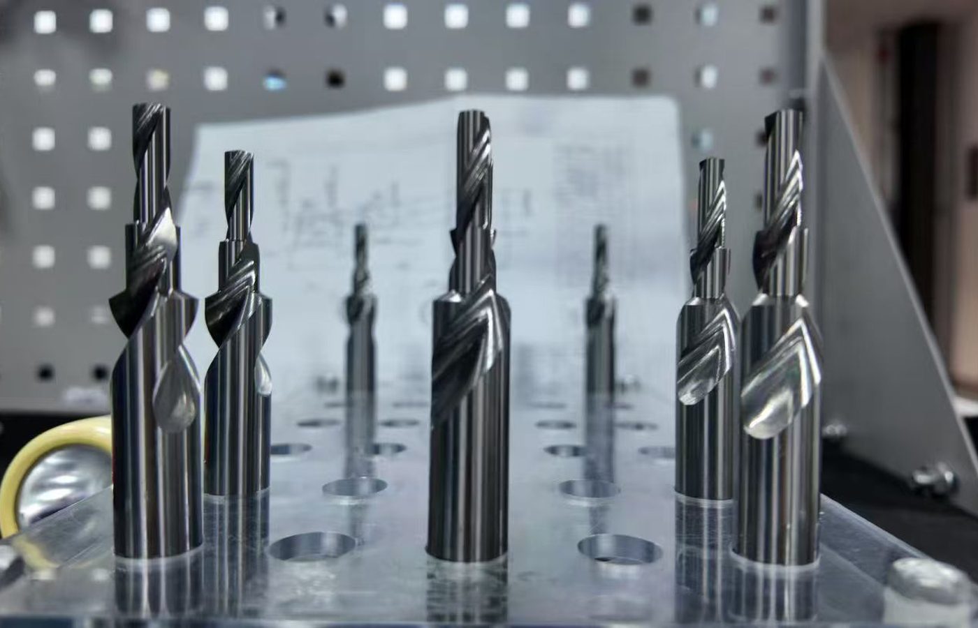
MSU’s carbide end mill range is organized by product type, cutting-end geometry and catalog series. Use the relevant product table to compare diameter, flute count, cutting length, overall length, corner or radius details and the available catalog fields. Confirm the exact catalog code, application and quantity before ordering.
Use product tables in this order:
The Downloads page is the document hub. Current product documents for this category include:
Open the document hub to use the current catalog copies and dimensional tables.
View End Mill Catalogs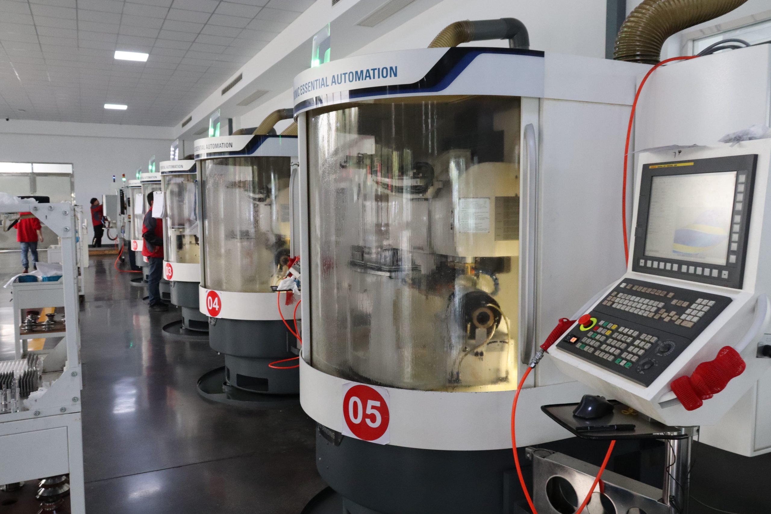
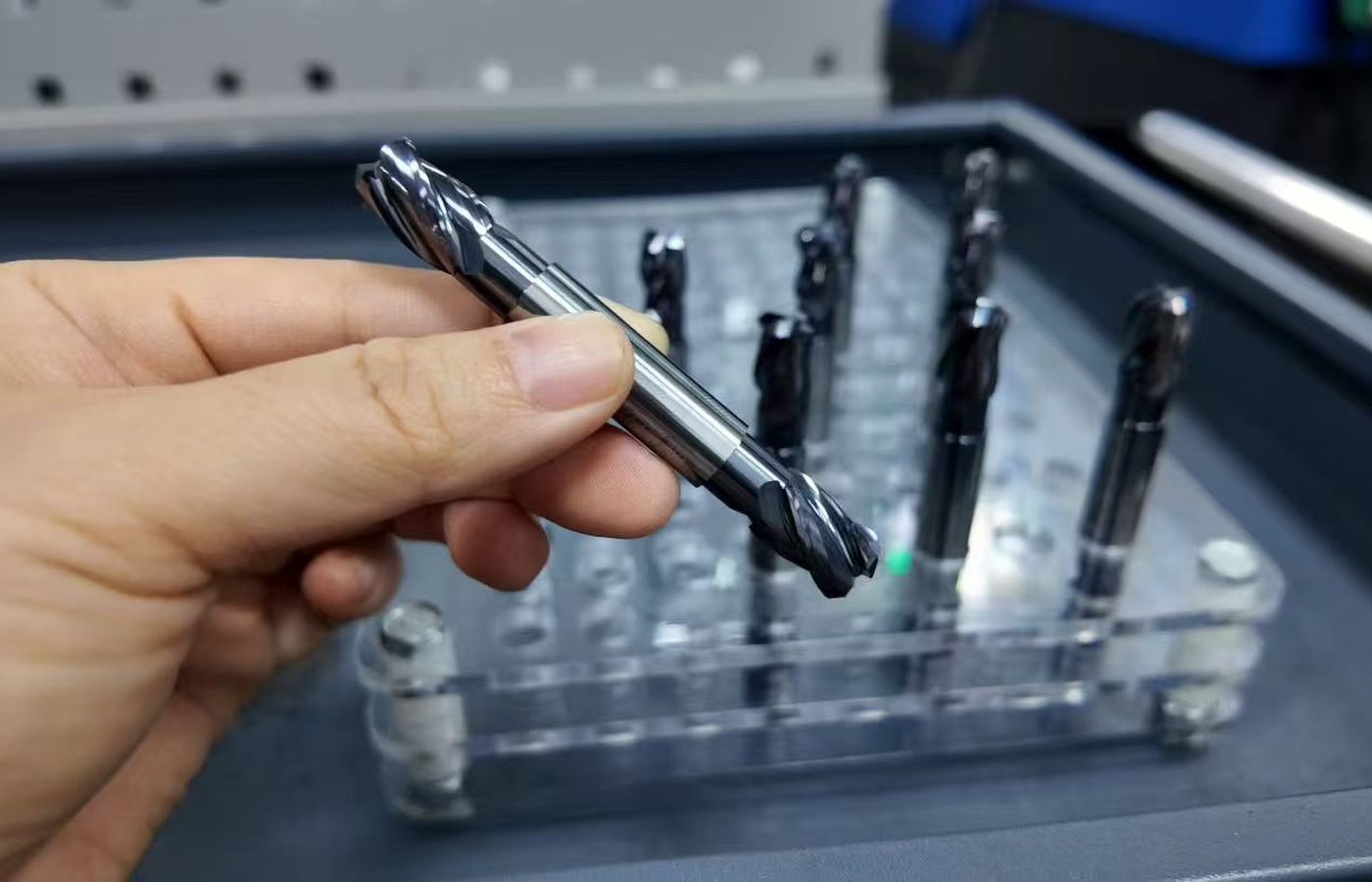
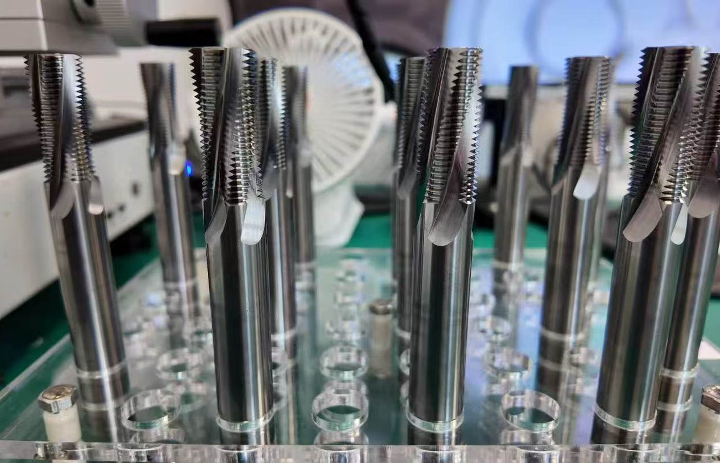
Carbide End Mills are an MSU-manufactured product line. The current catalogs establish the product families, catalog codes and dimensions.
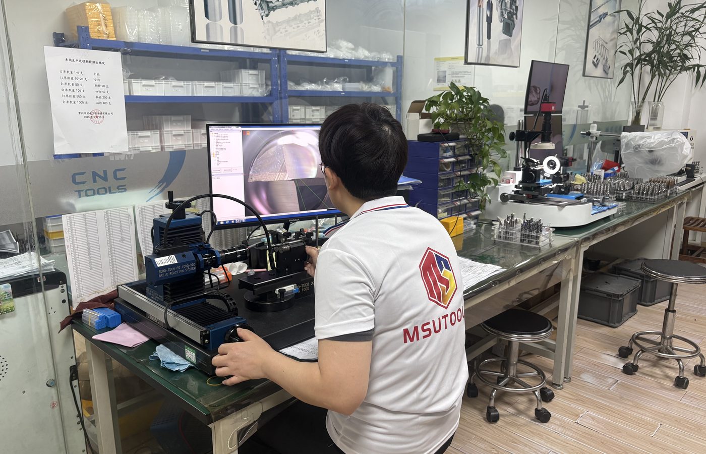
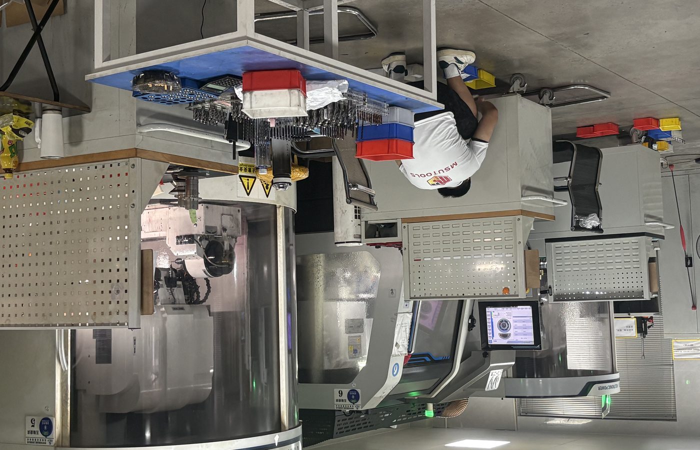
MSU’s round-tool workshop includes Walter HELITRONIC MICRO grinding equipment, and its inspection facilities include ZOLLER G3 measurement equipment. Model-specific dimensions, inspection items and acceptance requirements are confirmed against the selected catalog row, order or custom drawing.
Review MSU Factory for the manufacturing scope and Quality Control for the inspection and control workflow. Product-specific dimensions and requirements are confirmed against the selected catalog row, order or drawing.
See the manufacturing scope behind MSU-manufactured cutting-tool lines.
Review MSU Manufacturing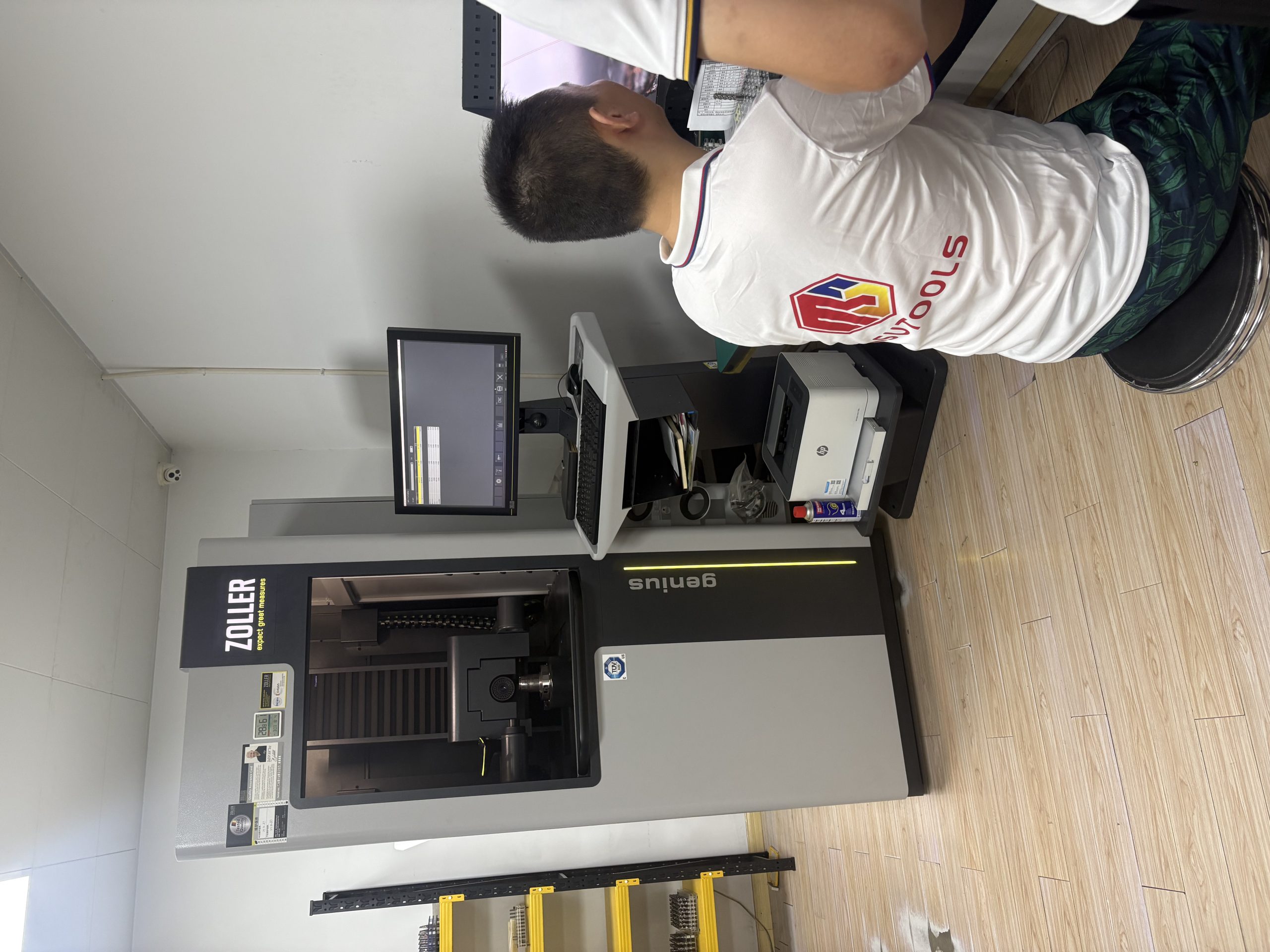
Send the catalog family or code when known, together with the application inputs. MOQ is normally 5–10 pieces, with the final quantity confirmed by product and quotation. Samples are charged according to the product, and sample freight is paid by the customer.
Completion of the whole order is guaranteed within 25–30 days from order placement. T/T with deposit and balance is supported; the percentages and payment milestones are stated in the quotation or order. EXW, FOB, CIF and DDP can be discussed and are confirmed by order, destination and feasibility. Quotations remain valid for 30 days.
For an issue after receipt, submit it within 30 days and include applicable evidence such as photos, batch number, measurement report or video. Each quality issue is reviewed case by case.
Use Ordering and Delivery for the shared commercial process and Downloads for current product documents. Inquiries are received by Maria at maria@msutools.com or +86 13973369578 by phone or WhatsApp. Browse Cutting Tool Resources for selection guides, product catalogs and ordering information.
Review the shared MOQ, sample, payment, delivery and issue-reporting rules before submitting the request.
Review Ordering and DeliveryStart with the drawing feature and operation, then confirm diameter, lengths, corner or radius data, flute count, workpiece and setup. A model is not selected from diameter alone.
Yes. Inch dimensions are included within the relevant geometry families. Check the current catalog for the available inch configurations.
Use the current product table to identify the geometry and catalog code, then send the application and quantity to MSU. Availability is confirmed for the specific inquiry.
Yes. Include the complete code, a catalog page or a drawing together with the application and quantity. MSU will compare the requirement with the current product range or review it as a custom request.
Yes. Drawings and technical files can be submitted for feasibility review. Dimensions, geometry, tolerance, substrate, coating, sample and batch conditions are confirmed by project and quotation.
Completion of the whole order is guaranteed within 25–30 days from order placement.