10D
3.1–20.0 mm
10 × diameter
Nominal depth designation; available cutting diameters extend to 20.0 mm.

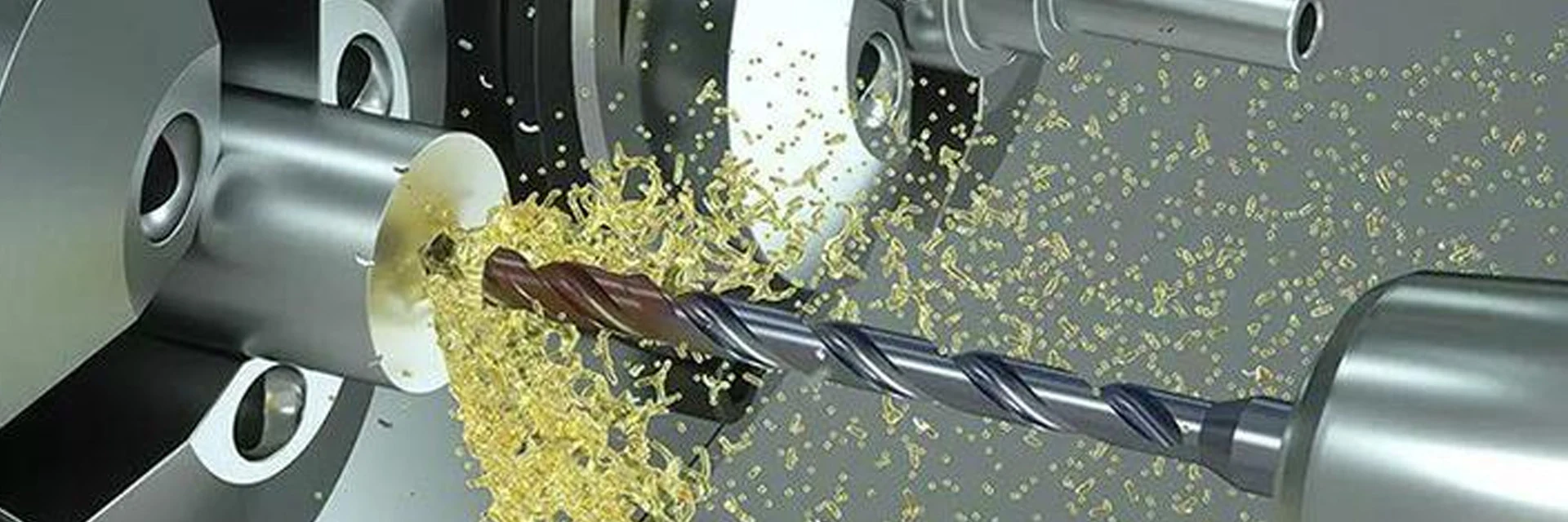
MSU solid carbide deep hole drills are available in 10D, 15D, 20D, 25D and 30D lengths. Choose the diameter and usable drilling depth, then check how the long tool will enter the hole, receive coolant and clear the part.
Compare flute length, shank dimensions and total length with the mounted setup. Entry guidance and the drilling cycle must suit the selected tool and workpiece.
Send the hole section and material, or your existing drill reference for a quote.
Find a Deep-Hole DrillDiameter coverage narrows at the longest lengths. Start with the required hole size and depth before comparing the full dimensions.
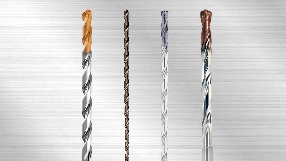
10D
3.1–20.0 mm
10 × diameter
Nominal depth designation; available cutting diameters extend to 20.0 mm.
15D
3.1–14.0 mm
15 × diameter
Nominal depth designation; available cutting diameters extend to 14.0 mm.
20D
3.1–14.0 mm
20 × diameter
Nominal depth designation; available cutting diameters extend to 14.0 mm.
25D
3.1–12.0 mm
25 × diameter
Nominal depth designation; available cutting diameters extend to 12.0 mm.
30D
3.1–10.0 mm
30 × diameter
Nominal depth designation; available cutting diameters extend to 10.0 mm.
For shorter holes, compare Solid Carbide Drills in 3D–8D. For small holes, compare Micro Drills; for replaceable cutting heads, compare Replaceable Head Drills. Use Solid Carbide Reamers to finish a prepared hole.
Check the required depth against the complete tool and holder assembly.
Check Deep-Hole DimensionsA long flute, a long shank and a long overall length affect different parts of the setup. Read these symbols from the deep-hole drill drawing.
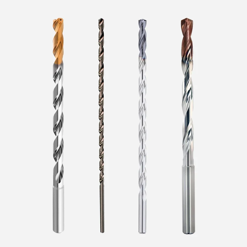
| Dimension | Meaning | What to compare | Why it matters |
|---|---|---|---|
| D1 | Cutting diameter | Required hole size | Selects the diameter of the cutting end |
| L1 | Flute length | Drilling depth and chip-clearance space | The whole flute length is not the usable full-diameter depth |
| D2 | Shank diameter | Holder clamping diameter | Determines the mechanical fit |
| L2 | Shank length | Required grip and projection | Affects how the tool can be mounted |
| L | Total length | Assembly length and machine travel | The complete tool must approach and withdraw clear of the part |
Compare the tool after it is clamped, including the holder nose and surrounding fixtures. Overall length alone does not tell you how much working reach remains.
Define the entry-guidance method and verify coolant delivery for the selected drill. Pressure, filtration and the entry and withdrawal sequence need tool-specific instructions.
Check entry guidance and coolant before setting the drilling cycle.
Check the Deep-Hole SetupThe hole section should show the entry face, full-diameter depth and breakthrough or blind bottom. Add any cross-hole that interrupts the cutting path.
A pilot diameter, coolant pressure or pecking cycle from another drill is not a setup instruction for this one. Agree the entry, cutting and withdrawal sequence for the chosen model.
For a special diameter, stepped hole or reach, email the part drawing to discuss Custom Cutting Tools.
Include the hole section and the coolant available on your machine.
Discuss a Deep-Hole ApplicationThe examples below all have a 6.0 mm cutting diameter. They show how flute and total length change with the depth designation; these are tool dimensions, not finished-hole depths.
6.0 mm example: L1 flute 78 mm; L total 116 mm; D2 shank 6 mm; L2 shank length 36 mm.
6.0 mm example: L1 flute 110 mm; L total 150 mm; D2 shank 6 mm; L2 shank length 36 mm.
6.0 mm example: L1 flute 140 mm; L total 180 mm; D2 shank 6 mm; L2 shank length 36 mm.
6.0 mm example: L1 flute 170 mm; L total 210 mm; D2 shank 6 mm; L2 shank length 36 mm.
6.0 mm example: L1 flute 200 mm; L total 240 mm; D2 shank 6 mm; L2 shank length 36 mm.
Check the dimensions again when changing diameter. Shank size and total length can change within the same depth designation.
Find the full dimension drawings in Downloads.
Use the full tool reference and dimension drawing when ordering.
View Tool DimensionsA long hole can meet diameter limits near the entrance while differing farther inside. State the measurement depths and any straightness or exit-position limits on the drawing.
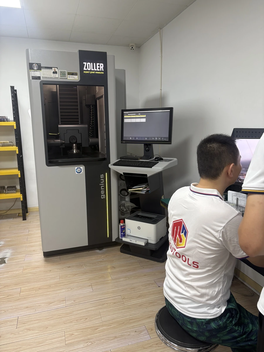
See MSU Factory and Quality Control for equipment and tool-measurement information.
For a drilling problem, retain the entry and withdrawal sequence, mounted projection and coolant conditions with the hole measurements. Identify where along the bore the deviation occurs.
Specify the tool measurements and records required before placing the order.
View Tool Inspection Information
The quotation will identify the selected tools or components, quantity, delivery terms and any agreed inspection records.
Use the full tool or component reference and quantity, or the previous order number. Mention any change to the application.
Email the hole drawing and material. Highlight the depth, tolerance, clearance or machining problem that needs attention.
MOQ is normally 5–10 pieces, confirmed for the selected product. Samples and sample freight are charged.
Production and shipping timing are confirmed in the quotation. T/T deposit and balance terms are stated with the order.
See Ordering and Delivery for purchasing terms and Downloads for dimension drawings.
Email Maria at maria@msutools.com or call/WhatsApp +86 13973369578.
Check the purchasing terms when confirming your tool reference, quantity and delivery.
View Ordering and DeliveryThe range covers 10D at 3.1–20.0 mm, 15D and 20D at 3.1–14.0 mm, 25D at 3.1–12.0 mm, and 30D at 3.1–10.0 mm. Select the exact diameter and working dimensions together.
No. 30D is a nominal depth designation. Check the usable drilling depth, point clearance and chip space for the chosen tool; the flute length is a separate dimension.
Match pilot diameter, depth and point geometry to the selected long drill and its entry sequence. Include the pilot tool already in use so the pair can be checked.
Pressure and flow requirements depend on the tool and application. Check the machine supply, holder connection and filtration against the instructions for the selected drill.
Use the drilling and withdrawal sequence specified for the chosen tool and material. Agree it before machining; the depth designation alone does not determine the cycle.
Record the hole size at defined depths and any straightness or exit-position deviation required by the drawing. Include the tool, mounted setup and drilling sequence with the results.
Send the full reference or the diameter and complete tool dimensions, plus the required hole depth. Mention changes to the entry guidance, workpiece or coolant setup.