External Turning Holders
- Operation
- Outside-diameter turning and profiling.
- Compare first
- Shank size, hand, approach angle and insert seat.
- Check before ordering
- Clearance at shoulders and along the intended profile.

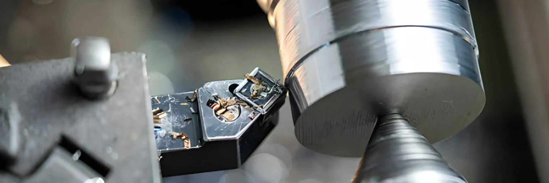
Turning tool holders position the insert for external turning, internal turning, threading, grooving or parting. Choose the operation first, then match the shank, hand and insert seat to your lathe setup.
For a replacement, compare the full holder and insert codes together. For a new setup, check tool access and the approach angle before choosing the holder size.
Send the holder code and quantity, or a part sketch if you need help choosing.
Find a Turning Holder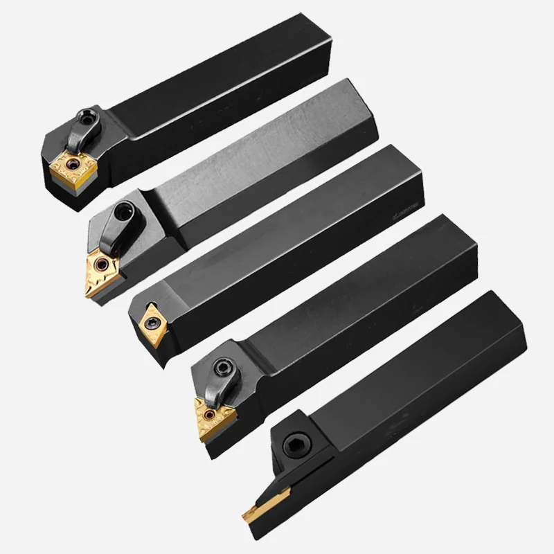
Check mounting dimensions and cutting orientation together. Then match the insert and clamping parts to the selected holder.
Match holder and insert
The insert must fit the holder seat and clamp. Its grade and cutting geometry should also suit the workpiece and operation.
Check the mounted orientation and access around your workpiece.
Check Turning SetupThe holder must fit the turret or toolpost and place the cutting edge where the part can be machined without interference.
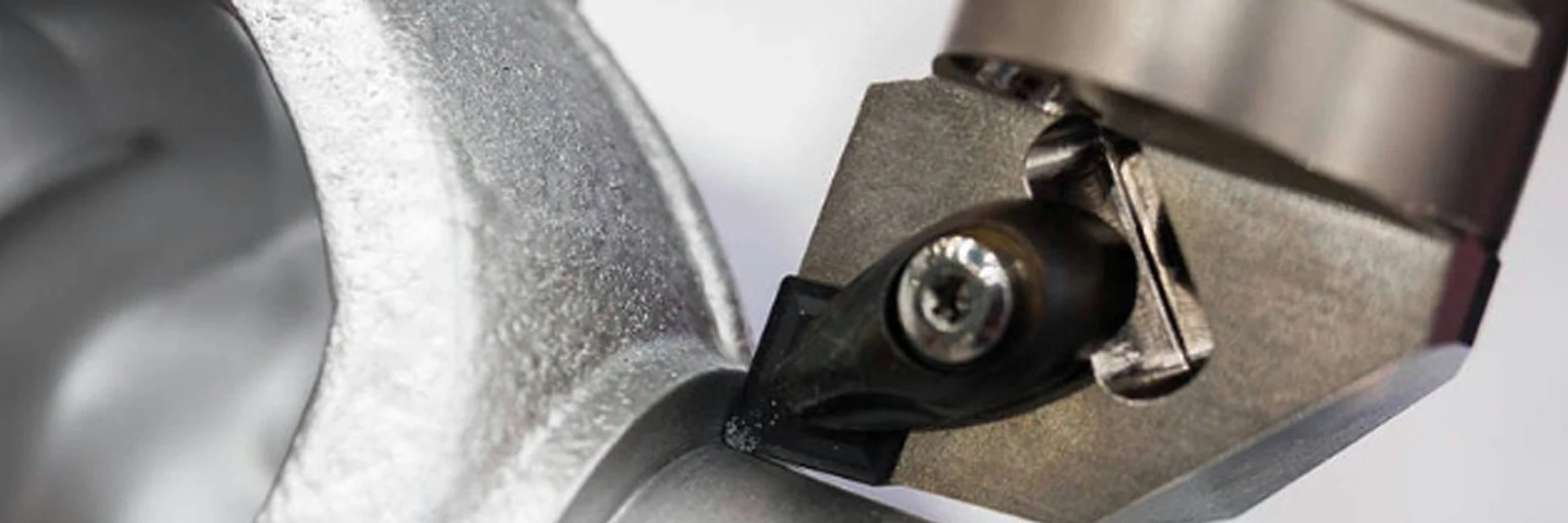
Check right-hand or left-hand selection against the installed position and cutting direction. A setup photo helps resolve an unfamiliar holder designation.
Check shoulders, fixtures and nearby turret tools through the intended movement, especially when a longer holder is needed.
Share a part or setup drawing when access determines the holder choice.
Discuss Your Turning SetupUse the full holder and insert references when replacing a working assembly. Keep the clamp, screw and shim references with them if those parts are needed.
A holder that accepts a similar insert shape may still use a different seat or clamping arrangement. A photo with the insert seated helps identify the parts when markings are unclear.
Find dimensional drawings and component references in Downloads.
Use the full model reference to find the corresponding drawing and components.
Find Drawings and ComponentsKeep tool dimensions and insert fit separate from the finished-part tolerance.
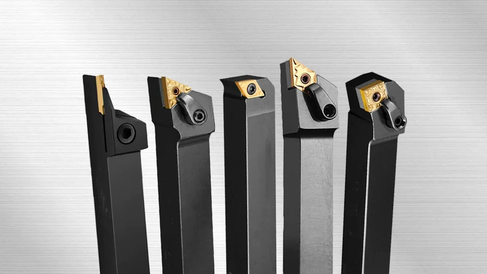
Identify the shank section, insert seat and clamping components on the holder drawing. Use the part drawing to state machining tolerances and the required finished surface.
If a dimensional report is required, name the measured holder features and tolerances. The quotation identifies the records available for the selected product.
Need inspection records? Include the measured features and test conditions in your enquiry.
View Quality ControlFor a repeat order, send the full model and quantity. For help choosing, email the part detail or current setup to Maria.
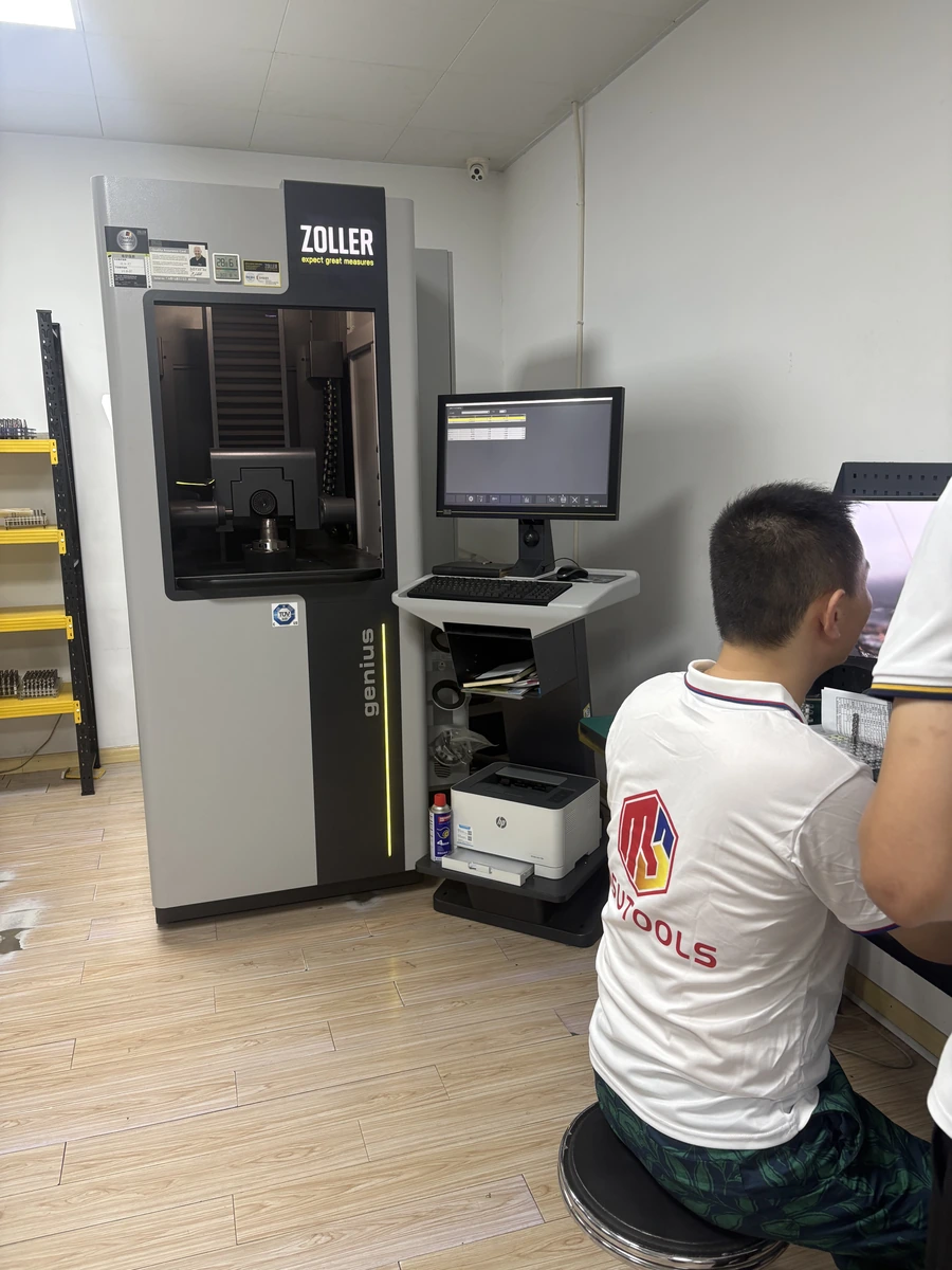
MOQ is normally 5–10 pieces, confirmed by quotation. Samples are charged; sample freight is paid by the customer.
Your quotation confirms production timing. Shipping time is stated separately.
Maria: maria@msutools.com · +86 13973369578 (phone or WhatsApp). Email drawings and photos.
Your quotation sets the payment, delivery and packaging terms for the order.
View Ordering InformationNo. Insert size, seating details and the clamping arrangement must also match the holder. Grade and cutting geometry are selected for the workpiece and operation.
Use the installed holder position and cutting direction. A setup photo helps identify the required orientation when the designation is unclear.
The surface to be machined, shoulder access and surrounding clearance determine the required approach. Compare the holder in its mounted position with the part profile.
The quotation identifies the supplied holder assembly and separate parts. Use the holder reference to identify any replacement clamping components.