
Carbide Insert Identification Guide
Read the complete insert marking to identify its shape and dimensions, then check the grade, chipbreaker and holder requirement separately. Match the marking to the exact MSU catalog model before ordering.
A partial marking can help identify the insert type. Model, size and ISO/ANSI holder fit need the complete code, catalog dimensions and assembly details.
Send a clear insert marking or catalog image for model and size confirmation.
Ask an Insert Identification QuestionScope and Intended Use
Use this resource to identify the correct insert family before checking a complete model and catalog row.
Use the complete marking and operation to choose one of the six Carbide Inserts types: Turning Inserts, Small Parts Machining Inserts, Grooving and Parting Inserts, Threading Inserts, Milling Inserts and Shallow Hole Drilling Inserts.
Use the Carbide Inserts pages and current catalog together. Exact model and dimension confirmation remains tied to the applicable catalog row.

Open Carbide Inserts when the product family is known.
View Carbide InsertsSelection Framework
Use the applicable catalog key to read the code. Separate the geometry and size designation from the grade and chipbreaker fields.
-
Shape
Identify shape first, then check access to the feature. In turning, a larger nose angle supports a stronger edge but can require more power and increase vibration; a smaller angle improves access.
-
Clearance or relief
Record the clearance designation and check the matching holder or cutter pocket. Clearance is one part of assembly fit, together with insert size, seat and clamping details.
-
Tolerance
Match the tolerance designation to the catalog key and dimensional requirements. Confirm the complete model rather than interpreting a single letter on its own.
-
Size and thickness
Match the size and thickness fields to the catalog dimension row.
-
Nose radius or corner detail
Match the radius to the drawing and cutting conditions. In turning, a larger nose radius strengthens the edge but increases radial force; a smaller radius can help with light cuts and vibration.
-
Chipbreaker, grade and hand
Grade and chipbreaker are separate selection fields. Grade is chosen for workpiece material and cutting conditions; chipbreaker geometry is matched to the operation’s feed and depth of cut. Confirm hand where the model includes it.
Code formats differ across insert types. Record the complete marking and match it to the catalog row, dimensions and holder or cutter-body specification before ordering.
Keep the geometry code, grade, chipbreaker and assembly details together.
Compare Insert Code FieldsCompare the Available Options
Choose the insert type that matches the operation, then compare its identification and assembly requirements.
Turning Inserts
Open product page →Identification focus
Check shape, clearance, tolerance, size, thickness and nose radius. Then select the grade for the material and the chipbreaker for finishing, medium cutting or roughing.
Confirm before ordering
Complete model, dimensions, hand and holder or system requirement.
Small Parts Machining Inserts
Open product page →Identification focus
Check the complete compact-insert model and dimensions. Add the holder code and feature drawing, since restricted access and small dimensions affect the assembly choice.
Confirm before ordering
Complete model, dimensions, application and holder or system requirement.
Grooving and Parting Inserts
Open product page →Identification focus
Check the grooving or parting system, cutting width and radius where specified. Match hand, blade or holder and the required groove depth to the exact model.
Confirm before ordering
Complete model, dimensions, hand and holder or system requirement.
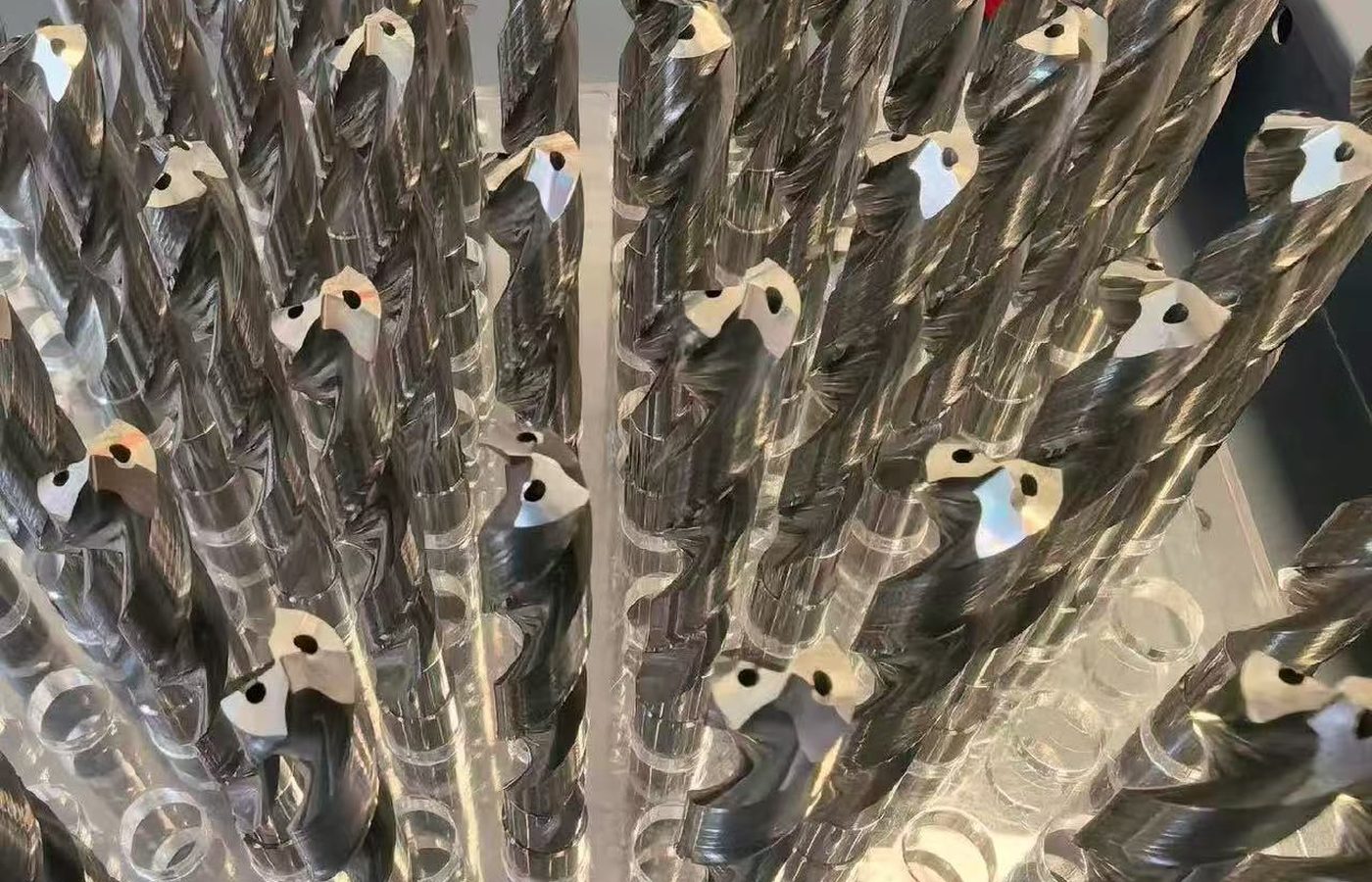
Threading Inserts
Open product page →Identification focus
Check internal or external thread, hand, profile and pitch. A full-profile insert is matched to a pitch and profile; a V-profile insert can cover a pitch range but does not form the thread crest.
Confirm before ordering
Complete model, dimensions, thread form and holder or system requirement.

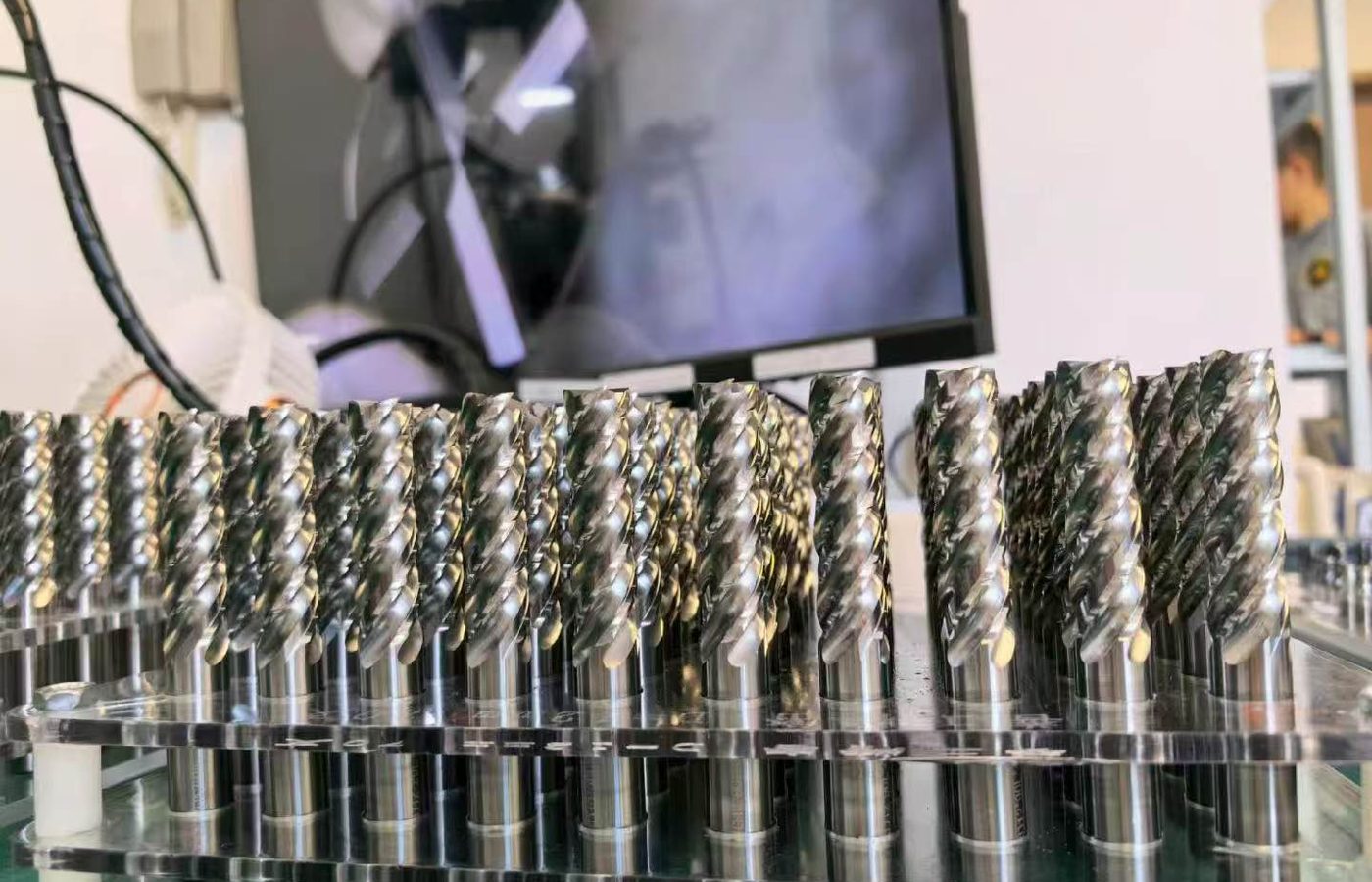
Milling Inserts
Open product page →Identification focus
Check the milling insert’s shape, size, thickness and corner geometry, then match grade and chipbreaker to the cut. Confirm the exact cutter-body pocket and clamping system.
Confirm before ordering
Complete model, dimensions and cutter-body or system requirement.
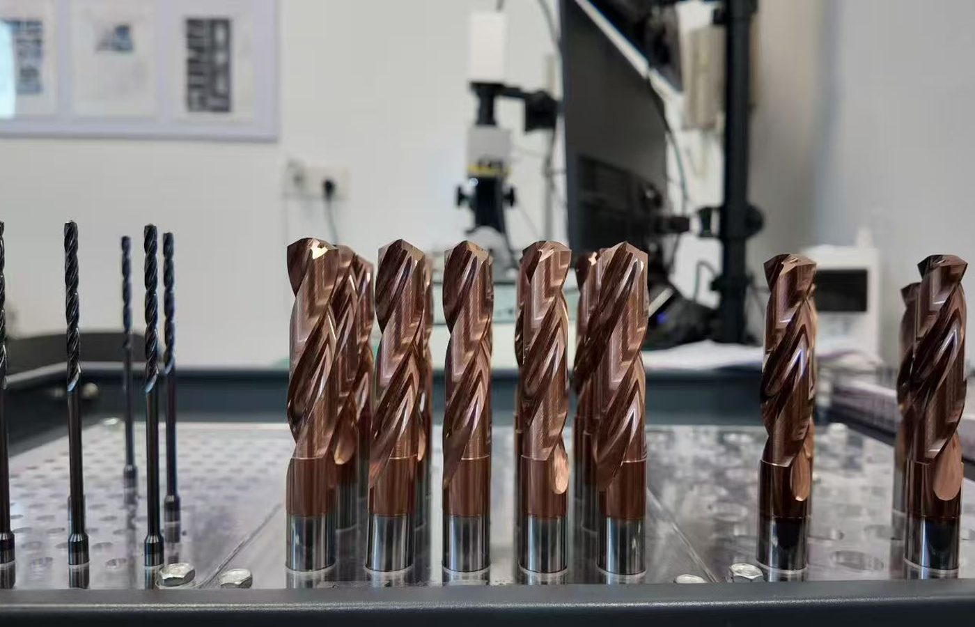
Shallow Hole Drilling Inserts
Open product page →Identification focus
Check the drilling insert model, dimensions and designated position in the drill body where specified. Match the complete drill-system code before selecting a replacement.
Confirm before ordering
Complete model, dimensions and drill-system requirement.
Use Downloads to find the complete model. Send the catalog page or clear tool marking if the row is difficult to read. MSU confirms availability for that model and grade.
Choose the insert type, then check the complete model and assembly fit.
Compare Insert TypesApply the Guide to MSU Products
Match the complete marking to the catalog row, then check the holder or cutter-body interface and cutting requirements.
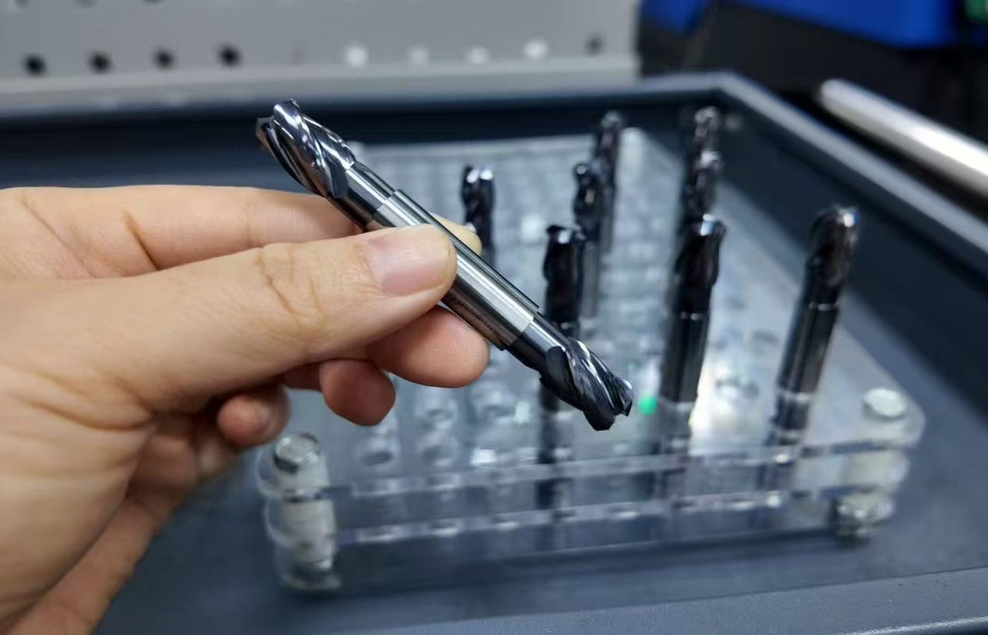
Start with the insert family
Start from Carbide Inserts and open the detailed product page for the operation.
Confirm the catalog row
Match the complete model, dimensions, grade, chipbreaker and hand to the current MSU catalog row for the selected insert type.
Downloads →Check the system interface
For assembly fit, check the exact insert and Toolholders specifications together. Include the holder or cutter-body code, insert seat and clamping details. A partial insert marking or general ISO/ANSI description is insufficient to confirm the assembly.
Send the full insert marking and catalog context when the product page alone cannot resolve the model.
Check Current Insert CatalogsModel Specifications and Assembly Fit
Use the complete marking and catalog dimensions to identify the model, then confirm the grade, chipbreaker and assembly.
Catalog model and dimensions
Check the complete model and dimensions in the current MSU insert catalog. If a photograph leaves any character unclear, send additional views, measured dimensions and the holder code for identification.
Replacement and compatibility
For a replacement insert, provide the full existing code, grade, chipbreaker and holder or cutter-body details. Match the dimensions and clamping interface before ordering; MSU confirms the available model and its intended application.
Find current catalogs in Downloads and inspection information for MSU-manufactured inserts in Quality Control. Include any dimensional or inspection-document requirement in your inquiry.
Send the complete marking, catalog row and assembly details for confirmation.
View Insert CatalogsAsk a Technical Question
Send the complete marking or catalog reference when the model, dimensions, grade, chipbreaker, hand or assembly fit needs confirmation.
Required details
Name, company, business email, country or region, insert marking or catalog reference, operation and question.
Optional details
Clear insert photographs, catalog screenshot, drawing, dimensions, workpiece, machine, cutter body or holder code, thread, groove or profile information, quantity, target date, phone and WhatsApp.
Upload guidance
Include both sides of the insert when markings differ, plus the relevant catalog page and holder or cutter-body images. Remove confidential information that is not needed for review.

Send the complete marking and catalog context to MSU for model confirmation.
Contact MSUCarbide Insert Identification Guide Questions
What is carbide insert nomenclature?
It is the structured code language used to describe insert fields such as shape, clearance, tolerance, size, thickness and corner detail. The applicable catalog key controls the interpretation.
Can I identify an insert from a partial code?
A partial code can suggest which fields need checking, but it is not enough to confirm a complete model, dimensions or availability.
Which fields should I check first?
Check shape, clearance, tolerance, size, thickness, nose radius or corner detail, then chipbreaker, grade and hand when those fields appear in the applicable catalog key.
Does every possible code combination exist?
Choose a complete model listed in the current catalog and ask MSU to confirm its grade, chipbreaker and availability.
Can this guide confirm ISO or ANSI compatibility?
Confirm fit from the complete insert model, dimensions and exact holder or cutter-body specification. Send both codes and the assembly details to MSU when a match needs checking.
Where are the current model and size records checked?
Use the current MSU insert catalog documents in Downloads and the Carbide Inserts product page.
What should I send when the marking is hard to read?
Send clear photographs of all marked surfaces, the catalog page or screenshot, dimensions and the holder or cutter-body information.