
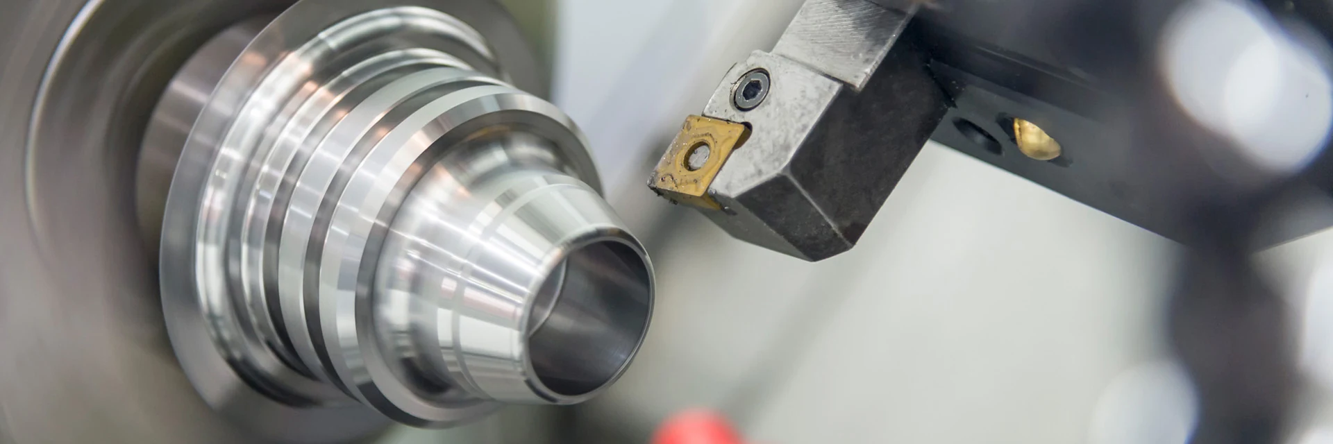
Turning Inserts
Choose carbide turning inserts for roughing, finishing, facing and profiling. The range includes negative and positive styles with different shapes, nose radii and chipbreakers.
Start with the holder and part profile, then match the cutting edge to depth of cut, feed and the workpiece. For an existing process, retain the geometry suffix and grade when identifying a replacement.
Send your insert and holder references, or a drawing of the feature you need to turn.
Find a Turning InsertChoose the Insert Style and Profile Access
Negative inserts have zero clearance on the insert itself and rely on the holder’s mounting geometry. Positive inserts have side clearance. Compare the complete tool’s access and stability before changing styles.
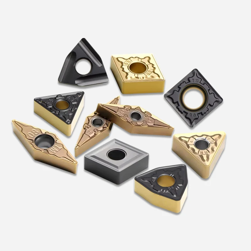
Negative Turning Inserts
Zero-clearance insert styles
Positive Turning Inserts
Insert styles with side clearance
Compare edge access, nose radius and chip control against the cut you need to make.
Compare Turning GeometryMatch Geometry to the Turning Cut
Roughing, finishing and interrupted cuts place different demands on the edge. Select the shape and radius with the holder, then choose the chipbreaker and grade for the operating conditions.

| Selection factor | What it changes | What to compare |
|---|---|---|
| Insert shape | Access to shoulders and profiles; corner strength | Part contour and holder approach angle |
| Positive or negative style | Side clearance and the supported cutting edge | Holder pocket and stability of the setup |
| Size and thickness | Seating and usable cutting-edge length | Holder specification and required depth of cut |
| Nose radius | Finish, chip formation and cutting forces | Feed, depth of cut and stiffness of the part |
| Chipbreaker | Chip curling and breaking within its working range | Roughing or finishing, material, feed and cut depth |
| Grade | Resistance to wear and edge damage | Material grade, hardness and interruptions |
| Edge condition | How the edge engages the material | Light finishing versus a heavier or interrupted cut |
| Complete designation | The exact replacement being ordered | Size code, geometry suffix and grade together |
Nose radius and stability
A larger nose radius strengthens the corner but can increase radial force. For a slender part or light finishing cut, compare a smaller radius with the required finish and feed.
Geometry and grade
A chipbreaker controls the chip within an intended cutting range; the grade addresses wear and edge loading. Changing one does not remove the need to check the other.
For a difficult cut, identify whether the issue is access, vibration, chip control or wear.
Check the Turning SetupReplacing an Insert or Starting a New Job
For a repeat order, the existing designation is the starting point. For a new job or a process change, explain the feature and cutting conditions so the edge can be selected for that task.
- Repeat orderKeep the full insert code, chipbreaker and grade, plus the holder reference.
- Part profileShow shoulders, radii and access restrictions on the drawing.
- MaterialState the actual grade and hardness, including heat treatment or scale.
- Cut typeDistinguish roughing from finishing and continuous from interrupted contact.
- Current processRecord depth of cut, feed, speed, coolant and mounted overhang.
- Problem to solveDescribe long chips, chatter, chipping, wear or the measured finish issue.
Email the part drawing and current cutting data when asking for a geometry or grade change.
Discuss a Turning JobCompare Turning Families and Example Designations
These examples show how size and geometry are carried in a designation. The selected grade is a separate order detail; keep it with the insert code.
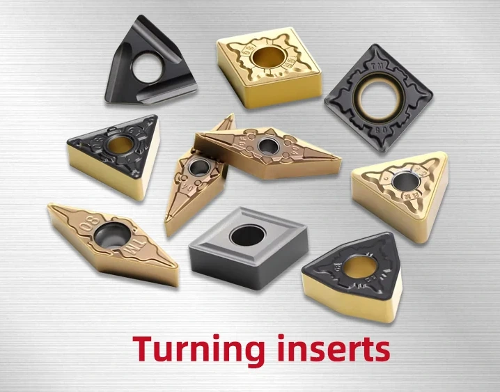
Positive Turning Inserts
CCMT060204-PM · 80° diamond; nose radius 0.4 mm.
DCMT070204-PM · 55° diamond; nose radius 0.4 mm.
SCMT09T304-PM · square; nose radius 0.4 mm.
TCMT110204-PM · triangle; nose radius 0.4 mm.
VBMT160404-PM · 35° diamond; nose radius 0.4 mm.
VCMT110304-MM · 35° diamond; nose radius 0.4 mm.
For small-component turning with CCGT, DCGT or TCGT, compare Small Parts Machining Inserts by nose shape and tool clearance.
Negative Turning Inserts
CNMG120408-PM · 80° diamond; nose radius 0.8 mm.
CNMA120408 · 80° diamond; nose radius 0.8 mm.
DNMG150408-PM · 55° diamond; nose radius 0.8 mm.
DNMA150408 · 55° diamond; nose radius 0.8 mm.
SNMG120408-PM · square; nose radius 0.8 mm.
SNMM250724-PH · square; nose radius 2.4 mm.
SNMA120408 · square; nose radius 0.8 mm.
TNMG160408-PM · triangle; nose radius 0.8 mm.
TNMA160408 · triangle; nose radius 0.8 mm.
VNMG160408-PM · 35° diamond; nose radius 0.8 mm.
VNMA160408 · 35° diamond; nose radius 0.8 mm.
WNMG080408-PM · trigon; nose radius 0.8 mm.
WNMA080408 · trigon; nose radius 0.8 mm.
Read the turning-insert drawing
- L and IC: cutting-edge length and inscribed circle
- S: insert thickness
- d: mounting-hole dimension
- Re: nose radius
- Geometry suffix and selected grade
Find the complete dimensional tables in Downloads. Match these dimensions to the holder specification before substituting an insert.
Use the dimension drawing and full designation to identify the insert you need.
View Insert DimensionsCheck the Insert and Turned Feature
Keep insert-size and edge requirements separate from finished-part acceptance. Use the component drawing to define diameter, profile and surface limits.
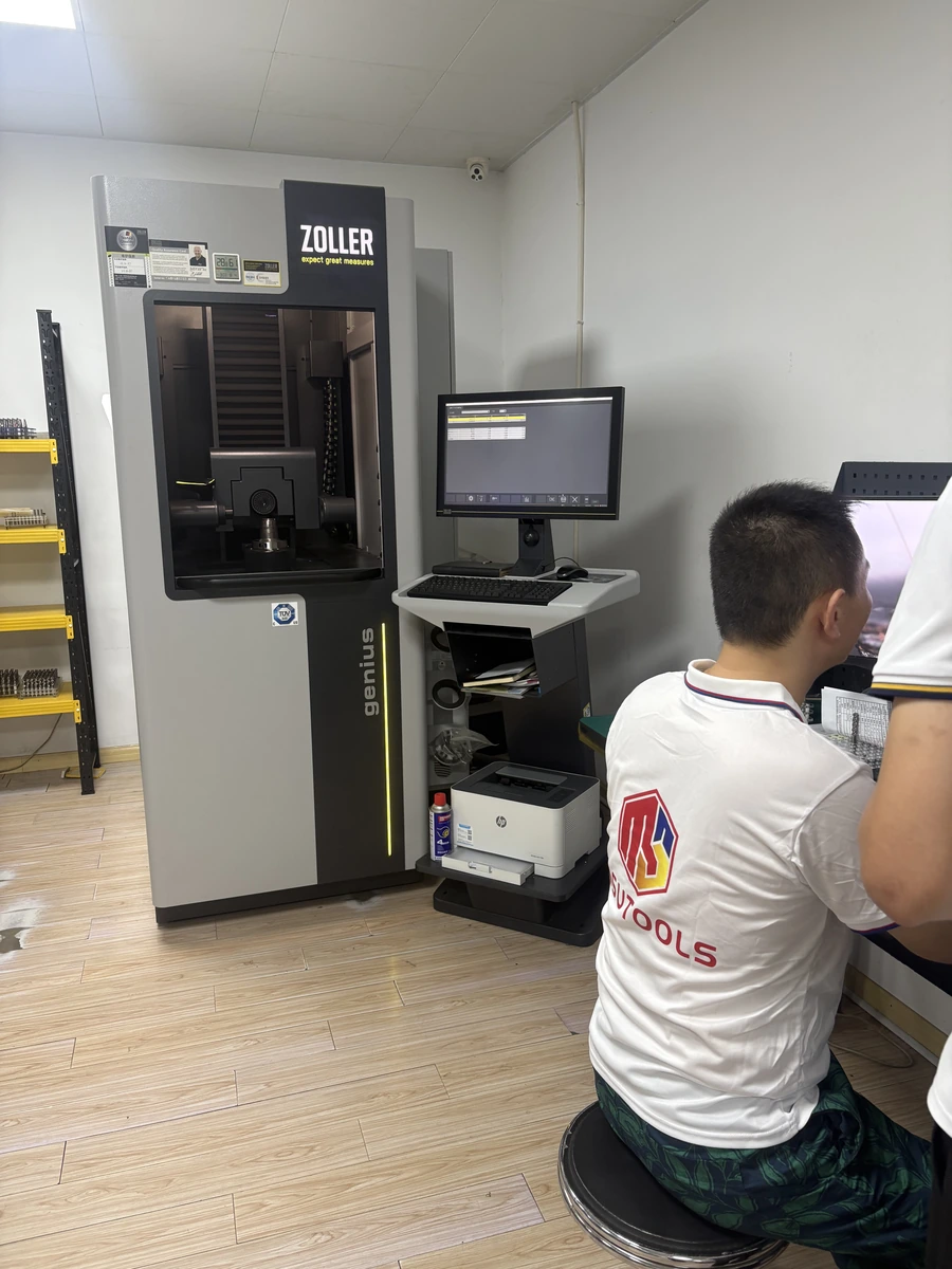
See MSU Factory and Quality Control for equipment and tool-measurement information.
For a dimensional or finish problem, retain the insert reference, cutting data and measurement positions with the trial result.
State any insert measurements and inspection records required before ordering.
View Inspection InformationOrder a Replacement or Discuss a Drawing
For a repeat order, use the full insert reference and grade. For a new application, email the drawing and identify the machining problem or feature that needs attention.
Repeat orders
Send the complete insert designation, geometry suffix, grade and quantity, or your previous order number.
New applications
Include the part profile, material, holder reference and roughing or finishing conditions. Email drawings to Maria using the address below.
MOQ and samples
MOQ is normally 5–10 pieces, confirmed for the selected product. Samples and sample freight are charged.
Delivery and payment
Availability, production and shipping timing are confirmed in the quotation. T/T deposit and balance terms are stated with the order.
Purchasing information
Ordering and Delivery covers purchasing terms; Downloads provides insert drawings.
Contact
Email Maria at maria@msutools.com or call/WhatsApp +86 13973369578.
Review the purchasing terms when confirming the selected insert, quantity and delivery.
View Ordering and DeliveryTurning Inserts Questions
Start with the holder and the available clearance. Then compare the required edge strength, cutting forces and stability. An insert style change usually requires checking the holder as well as the cutting conditions.
Compare radius with feed, depth of cut and part stiffness. A larger radius can increase radial force and vibration on a flexible setup. It is not an automatic finish improvement.
Check its recommended feed and depth-of-cut range. A light cut may not engage the chipbreaker effectively, which can leave long chips even when the insert fits the holder.
Review the interruptions, material and edge condition before reusing the grade. Include how the insert enters and leaves the cut and any chipping on the current edge.
Send the complete designation, chipbreaker, grade and holder reference. Include current cutting data and the result to be maintained or improved; similar size codes do not establish equivalent cutting behavior.
See Small Parts Machining Inserts for their shape and dimensional examples. Include the component diameter and tool-block clearance when discussing a small-parts setup.
Send the full insert designation, grade and quantity, or the previous order number. Mention any change to the material or cutting process.