
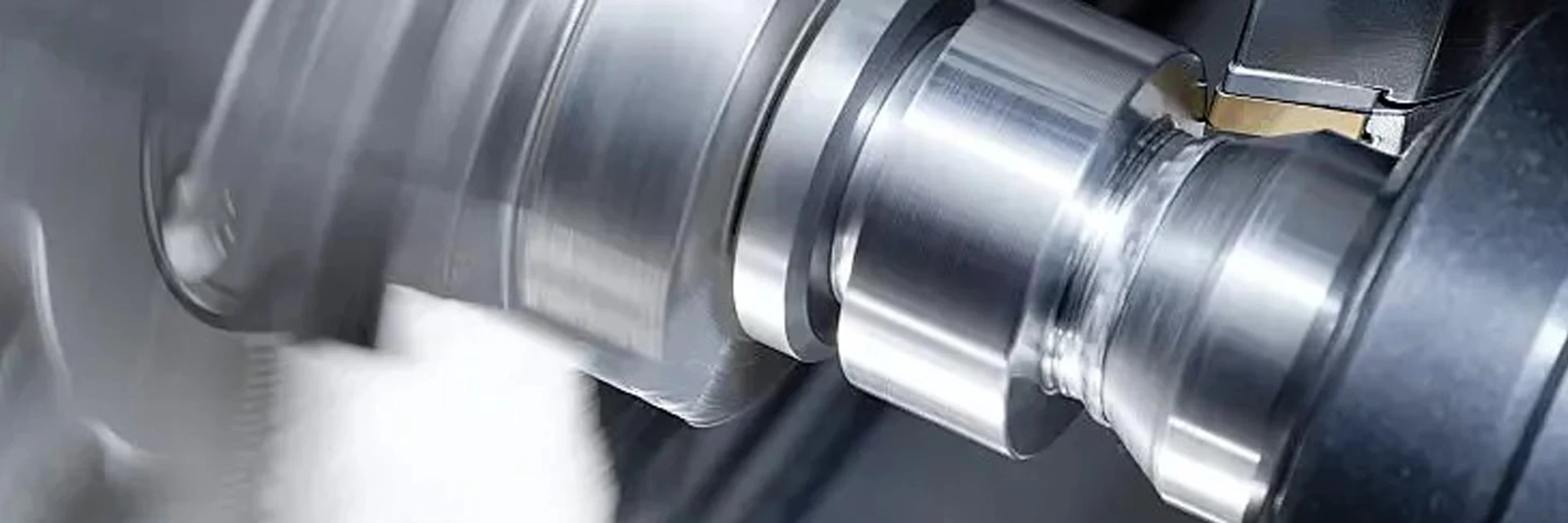
Small Parts Machining Inserts
Compare CCGT, DCGT and TCGT carbide inserts for small-parts turning. Their different corner shapes affect access around shoulders and close features; size and nose radius complete the comparison.
Choose for the actual component diameter, holder and available tool space. Include the workpiece material and finishing allowance when assessing an edge for a small or slender part.
Send the part drawing and holder reference, or the full insert code for a replacement.
Find a Small Parts InsertCompare the Corner Shape and Available Clearance
CCGT uses an 80° diamond, DCGT a 55° diamond and TCGT a triangular shape. The complete holder must also clear the part as the edge follows the profile.
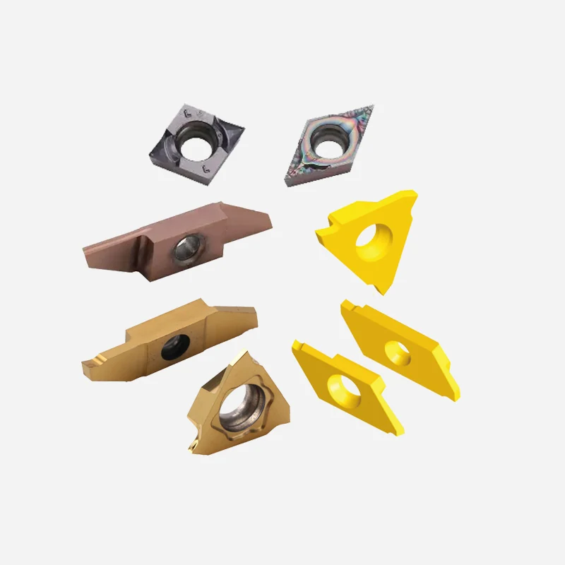
80° diamond. Compare the corner with the shoulder and profile that the holder must reach.
55° diamond. Check the narrower corner against the required profile and cutting load.
Triangular shape. Check the selected cutting corner and holder approach around the part.
For other turning geometries, compare Turning Inserts. For a groove, thread, milled feature or drilled hole, compare Grooving and Parting Inserts, Threading Inserts, Milling Inserts or Shallow Hole Drilling Inserts.
Compare the actual dimensions after checking which corner can reach the feature.
Compare Small Parts Insert ShapesMatch the Shape to the Part Profile
All three families have positive clearance. Their different shapes and seating dimensions require a matching holder pocket.

| Family | Insert shape | Access and fit check |
|---|---|---|
| CCGT | 80° diamond | Check shoulder clearance and the holder’s entering angle. |
| DCGT | 55° diamond | Compare profile access with the corner support needed for the cut. |
| TCGT | Triangle, 60° corners | Check the working corner, holder approach and clamping space. |
Changing from CCGT to DCGT or TCGT is a tooling change, not a drop-in shape substitution. Compare the holder pocket, center height and tool path.
Check support and clearance where the smallest feature is machined.
Check the Small-Parts SetupCheck the Edge at the Smallest Feature
On a slender part, cutting load and tool projection can affect size and finish. Describe the diameter at the cut and how the part is supported when discussing the edge geometry.
- Profile and accessShow the smallest diameter, shoulders and radii on the part drawing.
- Workpiece supportIdentify the grip length, unsupported length and any guide-bush or support arrangement.
- Finishing cutState the remaining allowance, feed and required surface condition.
- MaterialGive the actual grade, hardness and heat-treatment condition.
- Tool positionCheck the holder, block, center height, projection and nearby machine clearance.
- Current resultKeep the insert reference with size measurements, wear photos or a description of chatter.
Email a part section showing the close feature and available tool space.
Discuss a Small-Parts JobCompare Three Dimensional Examples
These MH-designation examples have a 0.4 mm nose radius. Their other dimensions differ. Select the grade for the material and process separately.

CCGT060204-MH · L 6.4 mm, IC 6.35 mm, S 2.38 mm, d 2.8 mm, Re 0.4 mm.
DCGT11T304-MH · L 11.6 mm, IC 9.525 mm, S 3.97 mm, d 4.4 mm, Re 0.4 mm.

TCGT110204-MH · L 11 mm, IC 6.35 mm, S 2.38 mm, d 2.8 mm, Re 0.4 mm.
Compare dimensions with the holder
- L: cutting-edge length
- IC: inscribed circle
- S: insert thickness
- d: mounting-hole dimension
- Re: nose radius
Find the full drawings in the Carbide Inserts catalog. For other positive and negative shapes, compare Turning Inserts.
Use the dimension drawing and full designation to identify the insert you need.
View Insert DimensionsMeasure the Insert and Small-Part Features
Use the component drawing to identify the small diameters, shoulders and surface features that need measurement. Agree any insert dimensions or edge records required with the order.
See MSU Factory and Quality Control for equipment and tool-measurement information.
Record the measurement locations and workpiece support with size readings. If results vary between parts, retain the same measurement method and the insert references used.
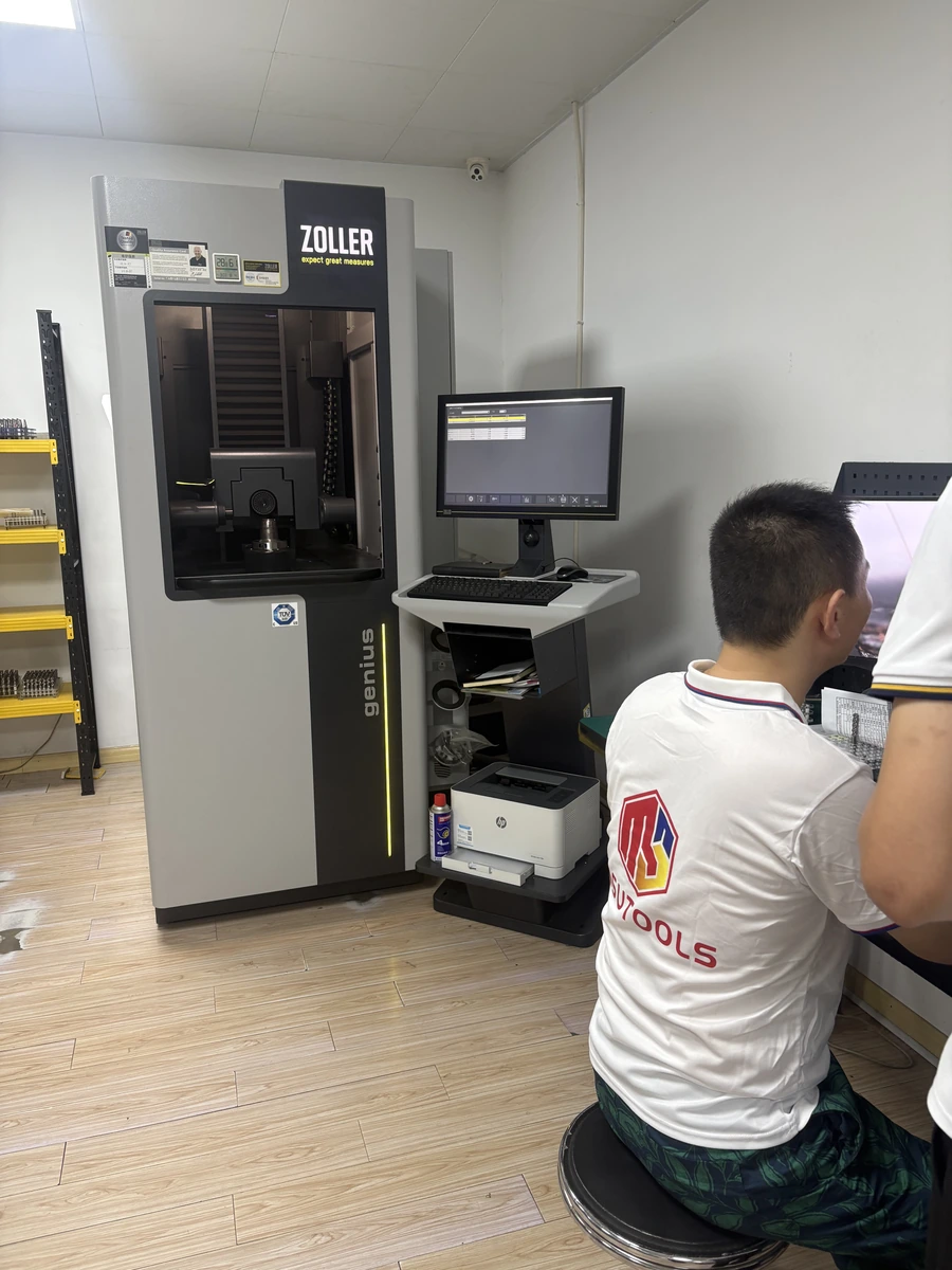
State any insert measurements and inspection records required before ordering.
View Inspection InformationOrder a Replacement or Discuss a Drawing
For a repeat order, use the full insert reference and grade. For a new application, email the drawing and identify the machining problem or feature that needs attention.
Repeat orders
Send the complete insert designation, geometry suffix, grade and quantity, or your previous order number.
New applications
Show the small diameter, close features, material and available tool-block clearance. Email drawings to Maria using the address below.
MOQ and samples
MOQ is normally 5–10 pieces, confirmed for the selected product. Samples and sample freight are charged.
Delivery and payment
Availability, production and shipping timing are confirmed in the quotation. T/T deposit and balance terms are stated with the order.
Purchasing information
Ordering and Delivery covers purchasing terms; Downloads provides insert drawings.
Contact
Email Maria at maria@msutools.com or call/WhatsApp +86 13973369578.
Review the purchasing terms when confirming the selected insert, quantity and delivery.
View Ordering and DeliverySmall Parts Machining Inserts Questions
Answers to common fit, selection and replacement questions.
Their shapes differ: CCGT is an 80° diamond, DCGT a 55° diamond and TCGT a triangle. Match the shape to the part profile and holder, then compare size, radius and edge geometry.
Treat that as a holder and tool-path change. Check the specified pocket shape, seating, clamping and center height before choosing the replacement.
Fit depends on the holder and tool block used on that machine. Send their references with the tool position and part drawing so clearance can be checked.
The radius must suit the feature, feed and remaining allowance. Compare the required finish with edge support and the stiffness of the workpiece; component size alone does not decide the radius.
No. The family identifies part of the geometry, while the grade is a separate selection. State the workpiece material and hardness together with the full insert designation.
Include the smallest diameter, unsupported length, holder projection, insert reference and cutting conditions. Keep the measured part sizes and the point in the operation where the problem occurs.
Send the complete code, geometry suffix, grade and quantity, or your previous order number. Note any change to the component or machine setup.