Boring Bars
- Purpose
- Insert-carrying bar entering the bore.
- Compare first
- Minimum bore, bar diameter, reach and insert connection.
- Check before ordering
- Bar material and clearance at the required depth.

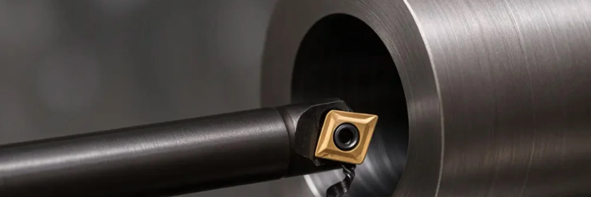
Boring tool holders, bars and modular components must reach the internal feature while leaving enough clearance inside the bore. Start with the existing hole, finished diameter and machining depth.
Then match the bar or boring head to the machine connection and working reach. For a modular assembly, check the connections between every component and the required coolant supply.
Send the bore dimensions and depth, or the existing assembly code for a replacement.
Find a Boring HolderCheck each component against the hole and the adjacent connection. An individual part fitting the machine does not confirm the whole assembly.
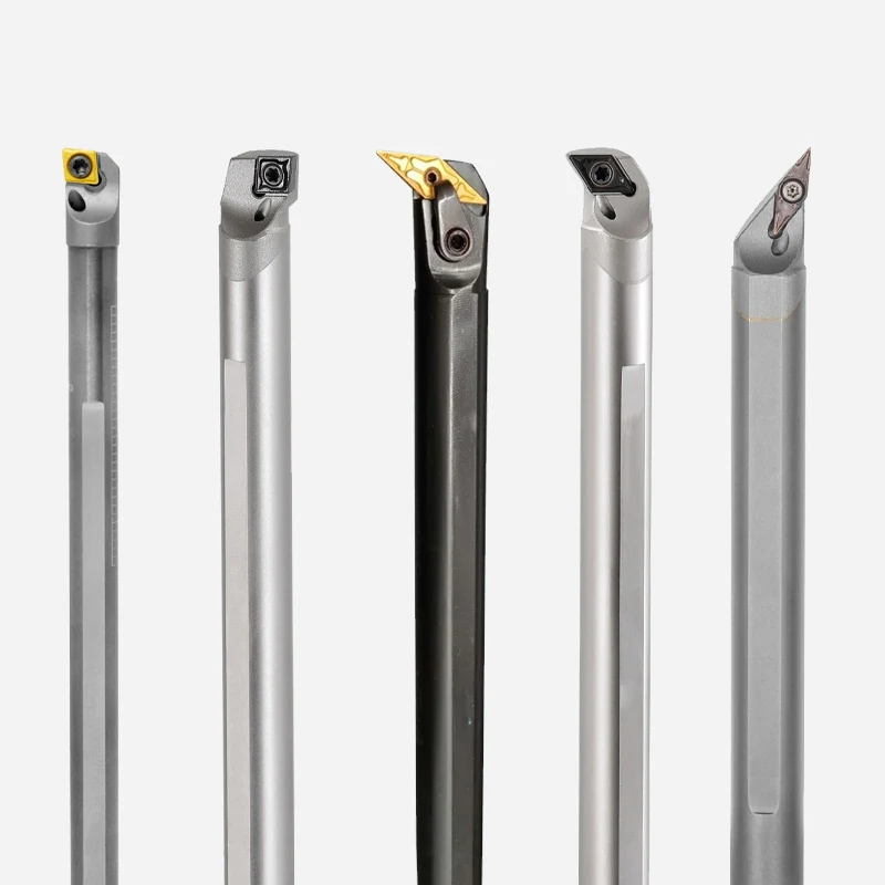
Use a drawing of the assembled tool to check bore entry, shoulder clearance and working reach. Identify the coolant path and insert connection before completing the component list.
Check the bore entry and required overhang before finalising the assembly.
Check Bore Access and ReachCheck the smallest opening the tool must pass through, then the distance to the machined feature. Finished bore diameter alone does not describe that access.
Use the shortest overhang that reaches the feature. Choose the largest bar diameter that fits the bore with the required clearance.
Email a section drawing when the internal shape or access is difficult to describe.
Discuss Your Boring SetupIdentify a modular assembly by its separate shank, adapter and head references. Overall assembled length alone does not identify the connections between those parts.
For a replacement oil-feed component, match its connection to the existing assembly and the required coolant path. Include the component marking or a drawing of its mating surfaces.
Find dimensional drawings and component references in Downloads.
Use the full model reference to find the corresponding drawing and components.
Find Drawings and ComponentsFinished-hole tolerance and surface finish are process requirements, not just holder dimensions.
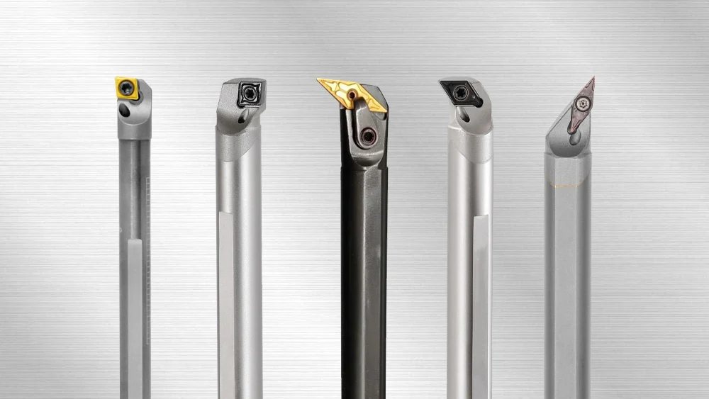
State the finished bore tolerance and surface requirement with the workpiece and setup conditions. A tool drawing identifies the mounting and cutting geometry; it does not establish the finished-hole result.
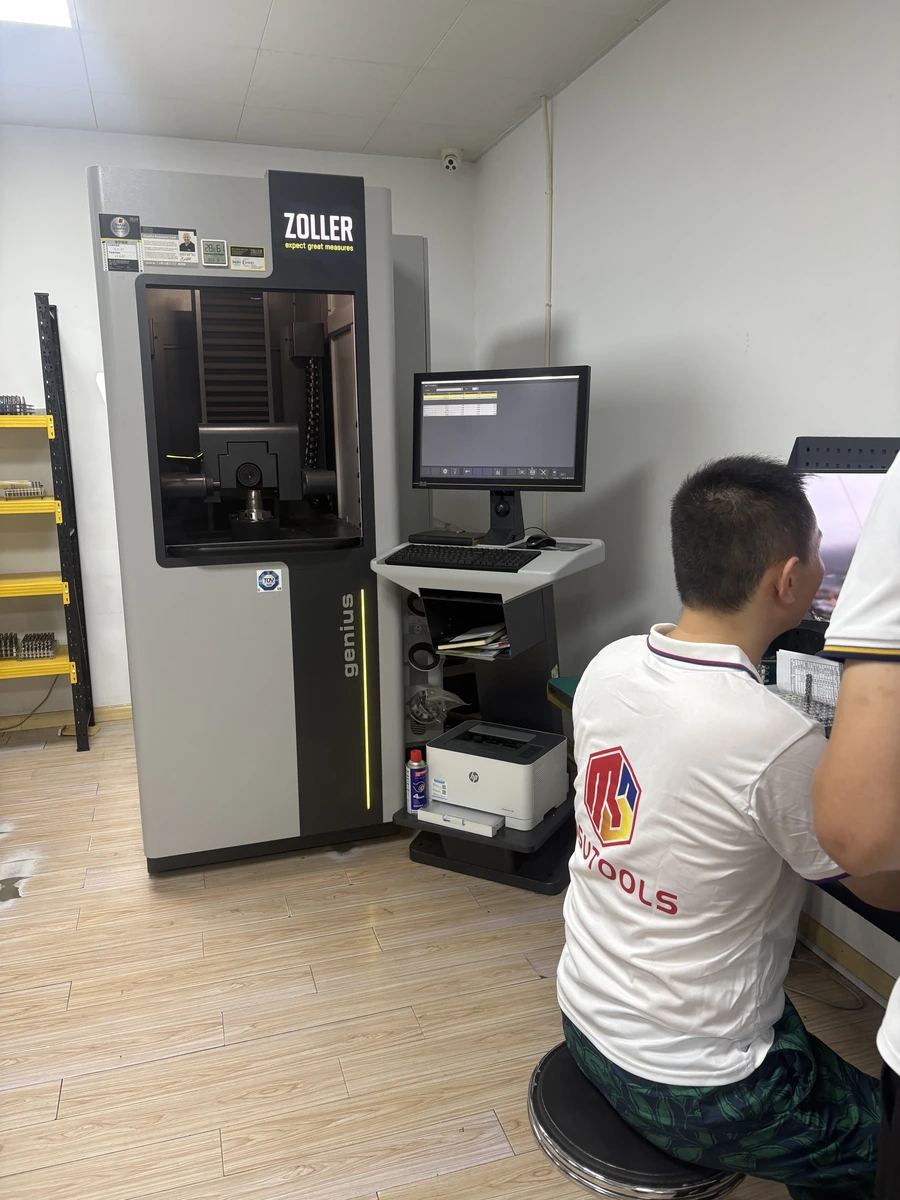
For a tool inspection report, identify the connections and dimensions to be measured. Confirm the report scope with the quotation.
Need inspection records? Include the measured features and test conditions in your enquiry.
View Quality ControlFor a repeat order, send the full model and quantity. For help choosing, email the part detail or current setup to Maria.
Normally 5–10 pieces; your quotation confirms the quantity for the selected product.
Samples are charged. Sample freight is paid by the customer.
Your quotation confirms production timing. Shipping time is stated separately.
Maria: maria@msutools.com · +86 13973369578 (phone or WhatsApp). Email drawings and photos.
Your quotation sets the payment, delivery and packaging terms for the order.
View Ordering InformationNo. The tool must pass through the starting hole and any smaller entry opening, then clear internal shoulders at the machining depth.
Only if the insert size, seating details and clamping components match the bar. A similar outline alone does not establish compatibility.
They can be quoted as the required assembly or as individual components. The quotation identifies the shank, adapters, head and other included parts.
No. Working reach is measured from the mounting reference to the cutting point. Supported length and the connections between components affect the assembled result.