Reference faces
Locate the groove depth
Dimension the groove position from an identified part face. This lets the L2 reference on the tool drawing be compared with the actual cutting depth.

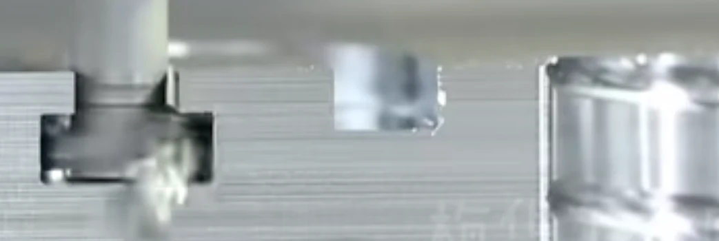
T-slot end mills cut the wider section beneath a slot opening. MSU’s 4TE four-flute carbide tools are selected by cutter-head diameter, cutting thickness and neck clearance.
Check how the cutter enters the feature before choosing a size. The head needs an entry path, and the neck must clear the slot opening throughout the cut.
Send the 4TE model and quantity, or a section drawing showing the slot and entry.
Find a T-Slot End MillThe 4TE cutting head reaches beneath the slot opening while the reduced neck provides clearance.
Check the complete path into the undercut. An open end or another suitable entry may be needed for the cutter head; the narrow slot opening alone does not establish access.
If a separate opening or pre-slot must be machined, compare Square End Mills for that operation. Explore other cutting profiles in Carbide End Mills.
Tool family
4-Flute T-Slot End Mill
Head + neck
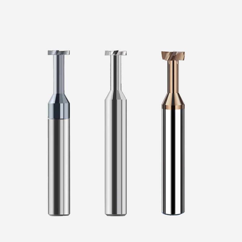
Compare the head, neck and length dimensions against the slot section.
Check T-Slot DimensionsCompare the cutting head with the finished undercut, then check the neck and reach against the entry path.
| Dimension | Match to the part | Why it matters |
|---|---|---|
| Head diameter d1 | Undercut width and entry opening | The head must fit the entry and reach the cutting surface |
| Head thickness L1 | Required groove height | Determines the cutting width along the tool axis |
| Neck diameter d2 | Opening width and side clearance | The neck needs clearance throughout the toolpath |
| Reach L2 | Depth of the undercut below the reference face | Check head position and clearance at the neck transition |
| Shank and overall length | Holder and usable projection | Check the assembled tool against the part and fixture |
L2 is measured to the reference shown on the tool drawing. It is not interchangeable with L1 or with a freely chosen neck length.
A section drawing makes the groove position and nearby obstructions visible.
Prepare the Slot DrawingSelected 4TE sizes in millimeters; the full range is available in Downloads.
| Model | Head d1 | Neck d2 | Thickness L1 | Reach L2 | Shank Dh6 | Overall L |
|---|---|---|---|---|---|---|
| 4TE001 | 4 | 2 | 1 | 6 | 4 | 50 |
| 4TE003 | 4 | 2 | 3 | 6 | 4 | 50 |
| 4TE010 | 10 | 6 | 1 | 10 | 10 | 75 |
| 4TE013 | 10 | 6 | 6 | 10 | 10 | 75 |
| 4TE022 | 16 | 8 | 1 | 20 | 16 | 80 |
| 4TE026 | 16 | 8 | 8 | 20 | 16 | 80 |
The same head diameter can have different cutting thicknesses. For example, 4TE010 and 4TE013 share a 10 mm head and 6 mm neck, with L1 values of 1 and 6 mm.
Use the drawing labels to identify the required 4TE size.
View 4TE DimensionsA section drawing locates the undercut relative to the opening. The End Mill Selection Guide covers the broader tool and setup choices.
Reference faces
Dimension the groove position from an identified part face. This lets the L2 reference on the tool drawing be compared with the actual cutting depth.
Nonstandard geometry
If the required head, neck or reach differs from the available sizes, email the section drawing for a custom-tool assessment.
Email the section and entry view for help matching a 4TE size.
Discuss a T-Slot DrawingSpecify tolerances for the cutting head separately from neck and holder clearance.
The MSU Factory has Walter HELITRONIC MICRO equipment; Quality Control facilities include a ZOLLER G3 measurement system.
Head diameter and thickness define the cutting envelope. Neck diameter and the L2 reference determine clearance below the slot opening; a head-size inspection alone does not establish that clearance.

Need a measurement report? State the tool dimensions to be reported with your enquiry.
Discuss Inspection RequirementsFor a repeat order, send the full model and quantity. For selection help, email the part detail and material to Maria.
Normally 5–10 pieces; the quotation confirms the quantity for your selected tools.
Samples are charged. Sample freight is paid by the customer.
Your quotation confirms production timing. Shipping time is stated separately.
Maria: maria@msutools.com · +86 13973369578 (phone or WhatsApp). Email drawings and photos.
Downloads has the full product drawings. See Ordering and Delivery for purchasing terms.
Share the slot cross-section so we can check head clearance and cutter size.
No. The head is wider than the neck and needs its own entry path, such as a suitable open end. The neck fitting the opening only establishes part of the clearance.
No. A head diameter can have several thicknesses. The 10 mm examples above differ in L1 even though their neck, reach and shank dimensions match.
No. L1 is the head thickness. L2 uses a separate reference on the 4TE drawing and must be compared with the groove position.
A square end mill can be considered for a separate opening or pre-slot. Reaching beneath the opening requires an appropriate undercutting geometry.