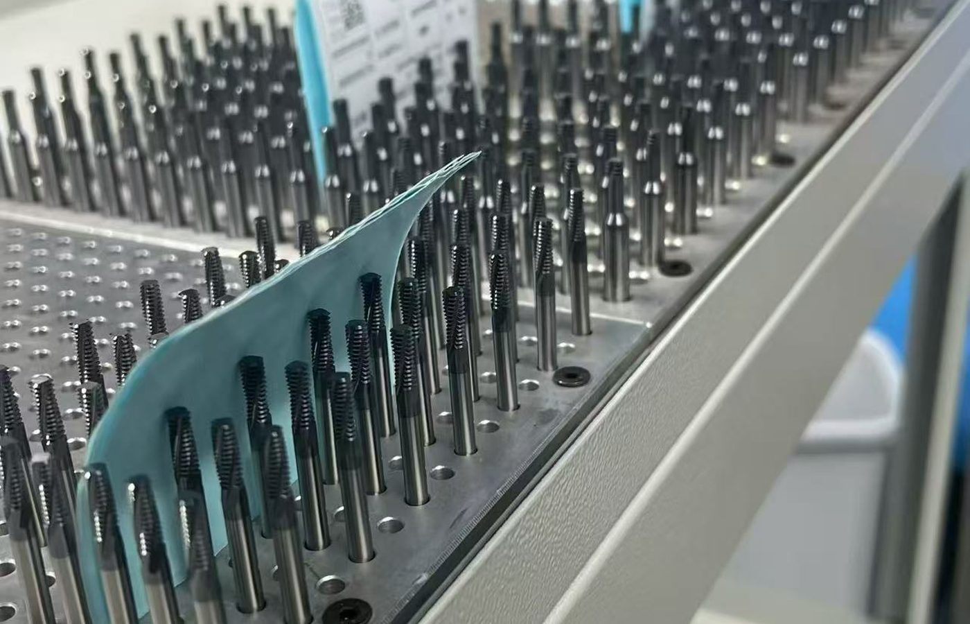
PCD Finishing Inserts
For a turned face, diameter or profile. Match the complete insert size, radius, usable diamond edge and fastening to the holder.


Choose PCD cutting tools for non-ferrous and non-metallic machining, including finishing inserts, milling cutters, reamers and custom profiles. Separate MCD single-crystal tools are available for applications with specific edge and surface requirements.
Match the diamond grade and edge geometry to the workpiece composition and the feature to be produced. For a replacement, retain the full tool reference, dimensions and holder connection.
Send the tool reference, or email the part drawing and required surface finish.
Find a PCD ToolA turned profile, milled face and precision hole need different cutting edges. Choose the tool form for the operation, then define its reach, connection and acceptance requirements.
For hardened-steel or cast-iron cutting, compare CBN / PCBN Tools. See PCD & CBN Tools for the cutting-material comparison, or discuss a special profile through Custom Cutting Tools.
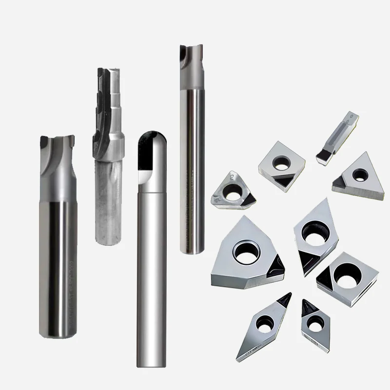
For a turned face, diameter or profile. Match the complete insert size, radius, usable diamond edge and fastening to the holder.
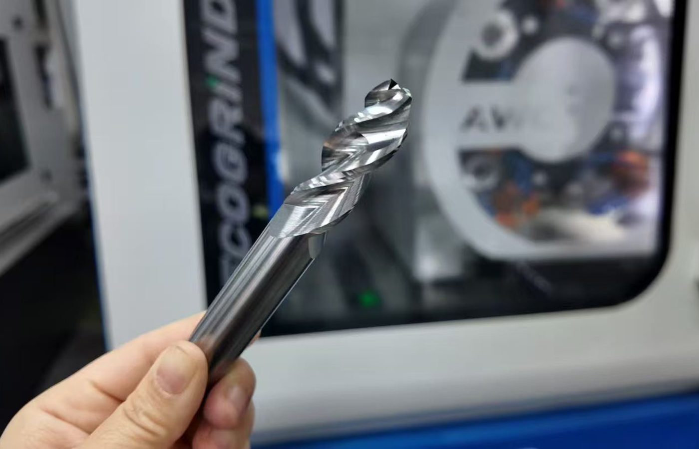
Single-crystal diamond tools for specified cutting profiles and surface requirements. Options include milling and chamfering forms; state the required edge geometry.
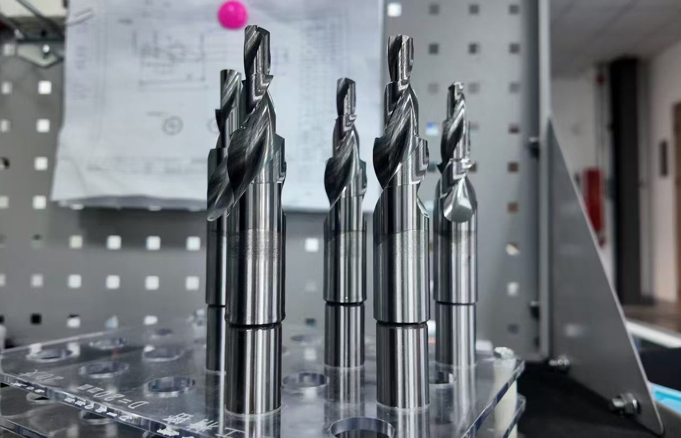
For milled faces and profiles. Define cutting diameter, corner or profile radius, edge count and the shank or machine connection.
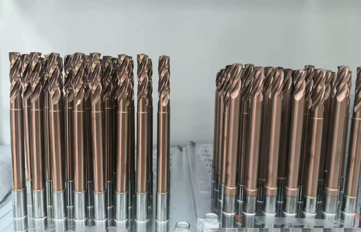
For finishing an existing hole. State pre-hole size, final diameter and tolerance, working length and any steps or interruptions.
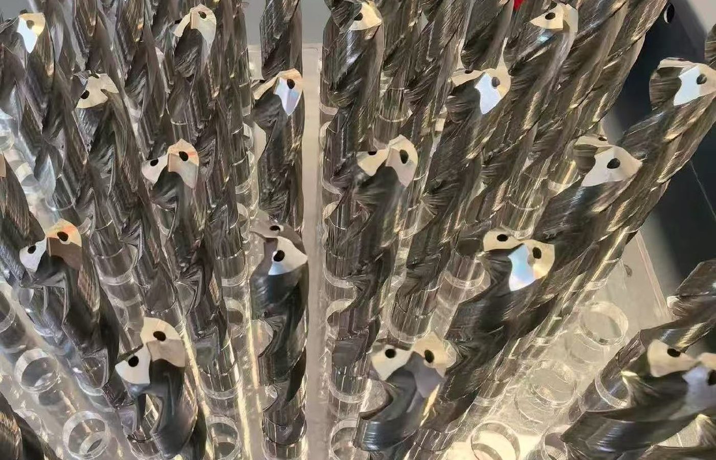
For a stepped, formed or clearance-sensitive feature. Provide the tool and part drawings with the critical dimensions and revision.
Choose the cutting form that matches the feature and tool connection.
Compare PCD Tool FormsPCD contains bonded diamond grains; MCD is a single crystal. Their edge structures differ, so the material and edge specification should stay with the tool designation.
A fine edge and a wear-resistant grade address different parts of the job. Compare the workpiece composition and the actual finish limit before changing the diamond material.
| Tool form | Feature | Geometry and fit | Acceptance to define |
|---|---|---|---|
| PCD finishing insert | Turned face, diameter or profile | Insert seat, radius, cutting-edge length and direction. | Diameter, profile and surface finish. |
| MCD tool | Specified edge or surface requirement | Single-crystal edge profile, relief and mounting. | Surface measurement and profile limits. |
| PCD milling cutter | Milled face, shoulder or contour | Diameter, radius, edge count, reach and connection. | Surface marks, flatness or feature dimensions. |
| PCD reamer | Finished hole | Diameter, cutting length, shank and pre-hole allowance. | Hole size, form and surface finish. |
| Custom PCD tool | Stepped or formed feature | Drawing revision, working envelope and interface. | Critical tolerances and measurement locations. |
Check the edge profile, working reach and mounting together.
Check the PCD ApplicationDefine what the finished feature must achieve before changing the tool. Keep the material composition, process conditions and inspection method with the drawing.
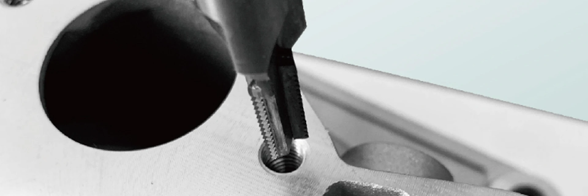
Specify the result to measure
Use a numerical finish requirement and measurement method where specified. A photograph alone does not define surface acceptance.
For a repeat order, retain the approved edge profile and grade. For a change, record the old tool and trial conditions so the results can be compared.
Email the drawing and state the dimensional or finish requirement to meet.
Discuss a PCD ToolPCD grain size affects the balance between edge quality and wear resistance. Grade examples help narrow the choice, while the complete tool drawing establishes geometry and mounting.
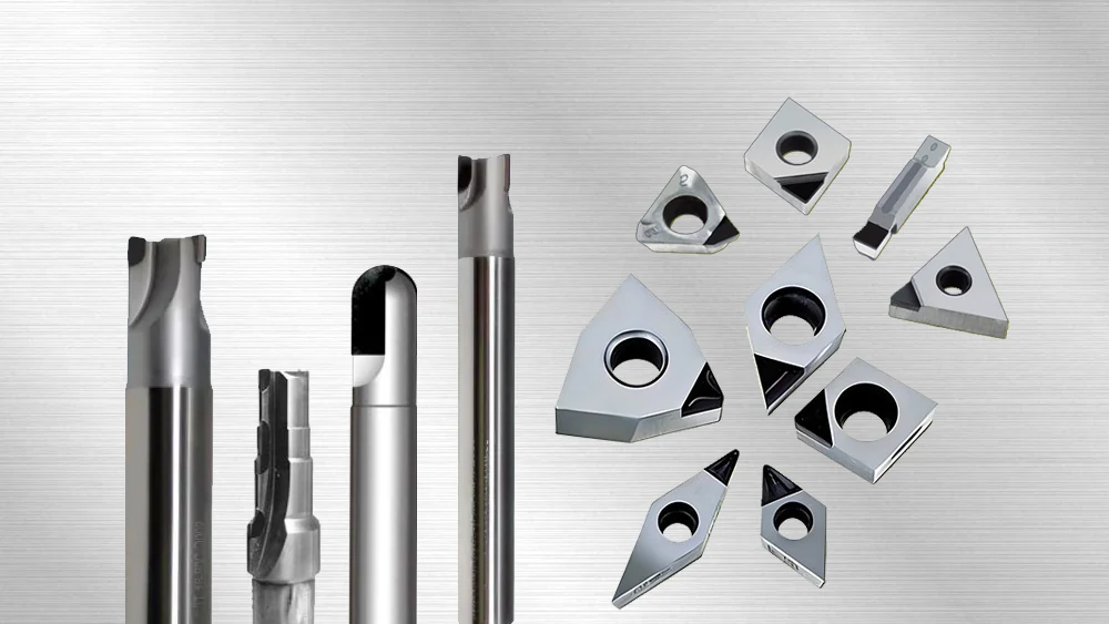
An option where edge quality is a priority, with applications including copper and aluminum. Discuss the required surface and interruptions with the tool geometry.
Applications include copper alloys and graphite. Compare abrasive content, edge quality and the required wear resistance for the actual workpiece.
YD120 is a medium-grain option with copper and aluminum applications. YD130 is a coarser option with plastics and reinforced-material applications; assess edge finish and impact conditions.
One single-crystal milling tool example has a 4 mm cutting diameter, 3 mm cutting length, 6 mm shank and 40 mm overall length. Select the required edge profile and material explicitly.
Keep cutting diameter, profile, edge count, working length and mounting dimensions together. For stepped tools, show the axial positions and tolerances of every cutting feature.
Keep the selected diamond grade with the full tool drawing or code.
View PCD Tool DimensionsAgree which tool dimensions and edge features need measurement. Keep the part-surface requirement separate from the tool inspection record.
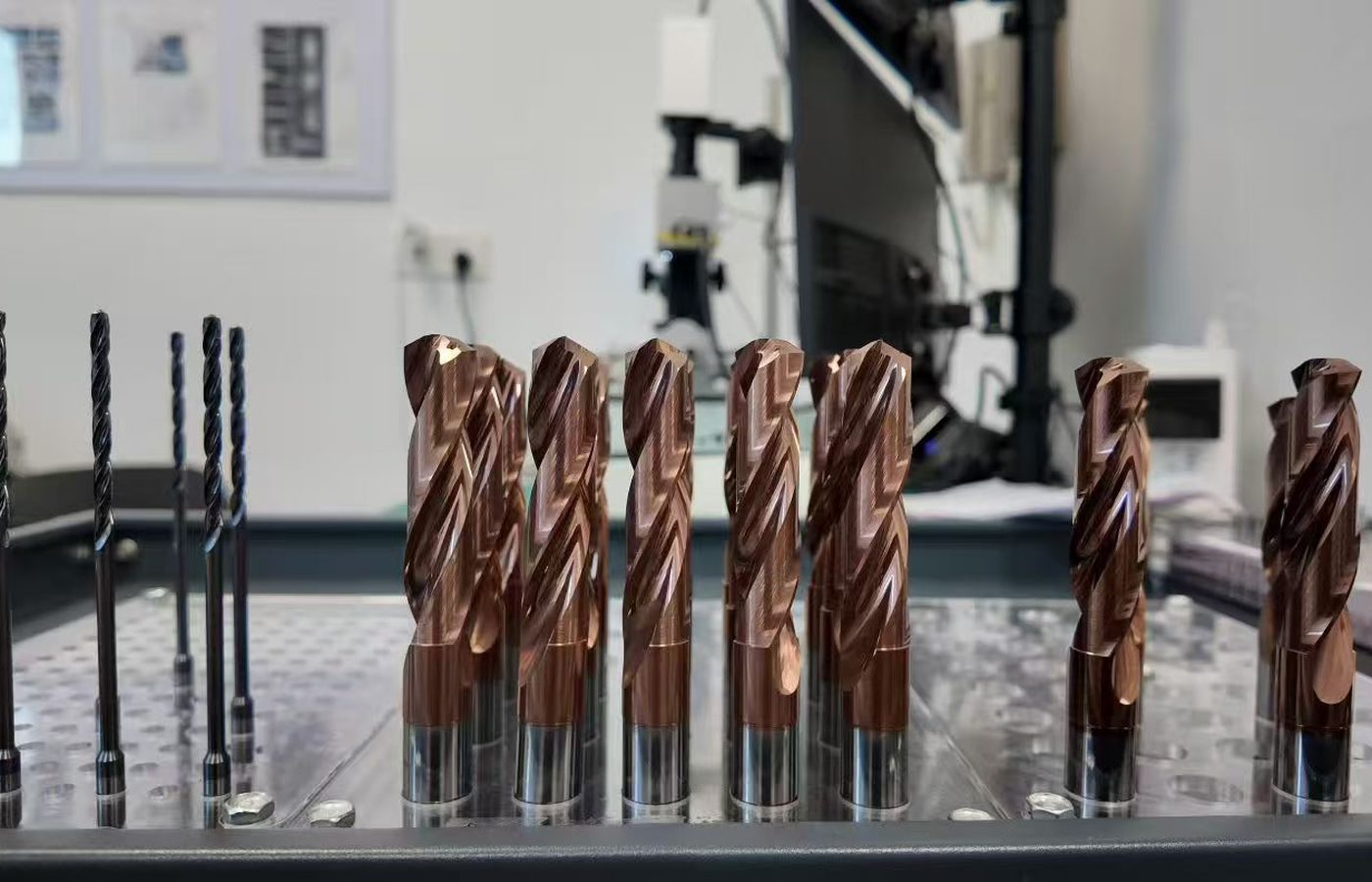
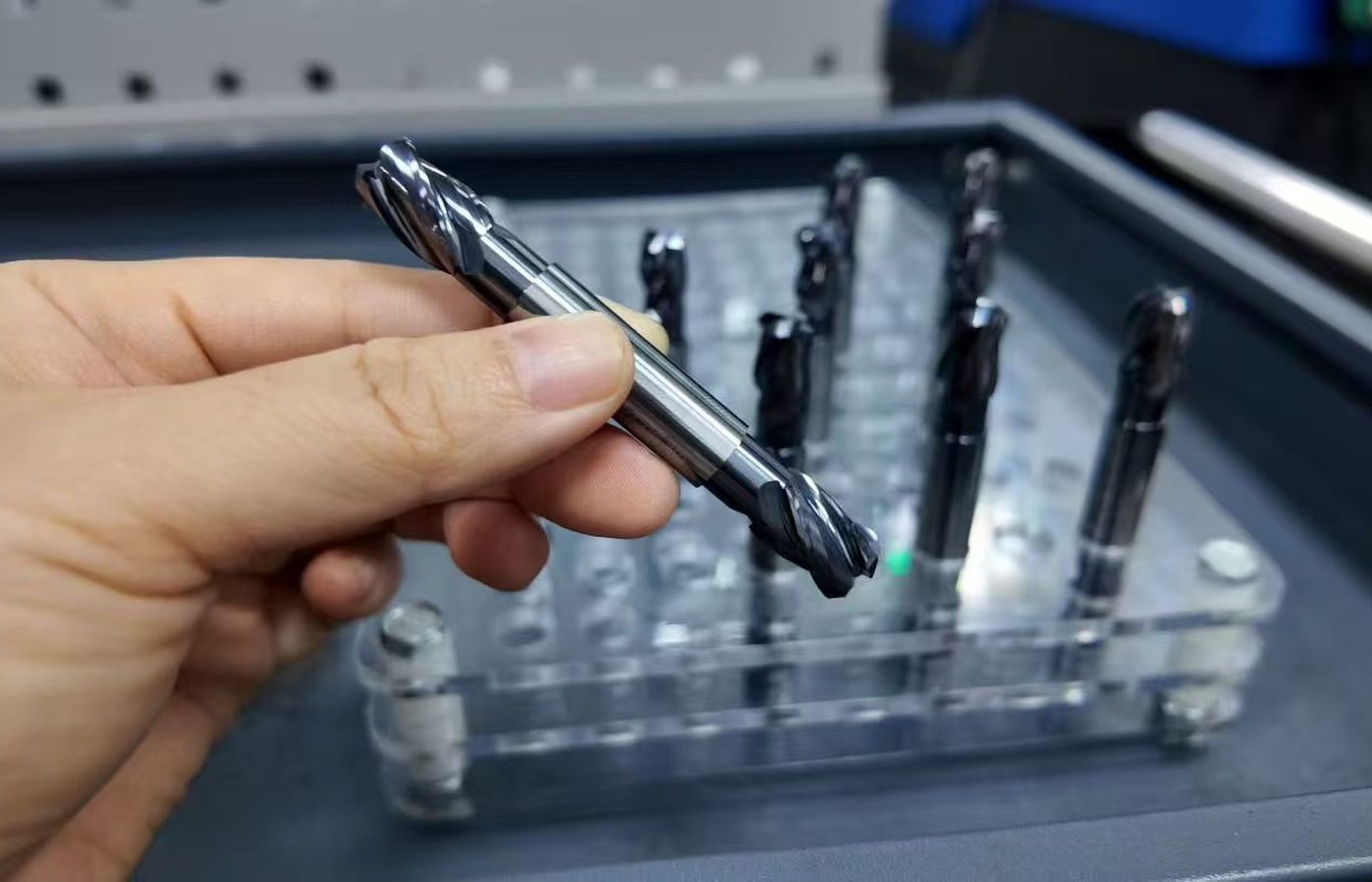
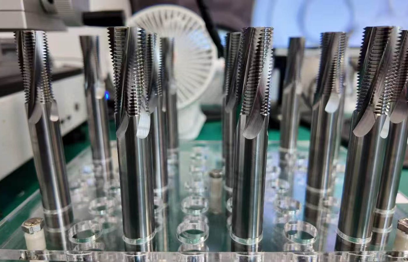
For an insert, specify radius, edge condition and seat dimensions. For a cutter or reamer, specify cutting diameter, profile, working length and mounting dimensions.
Specify any dimensional report, edge inspection or material identification record needed with the order. Agree the measured features and document scope before ordering.
For a machining trial, record the tool reference and cutting conditions with the measured part dimensions and surface finish. See Quality Control for available inspection information.
Specify critical edge and dimensional measurements before ordering.
View Inspection InformationFor a repeat order, send the complete tool reference and quantity. For a new job, email the drawing and describe the feature or machining problem. Ordering and Delivery covers MOQ, payment and shipping. Tool drawings are available in Downloads.
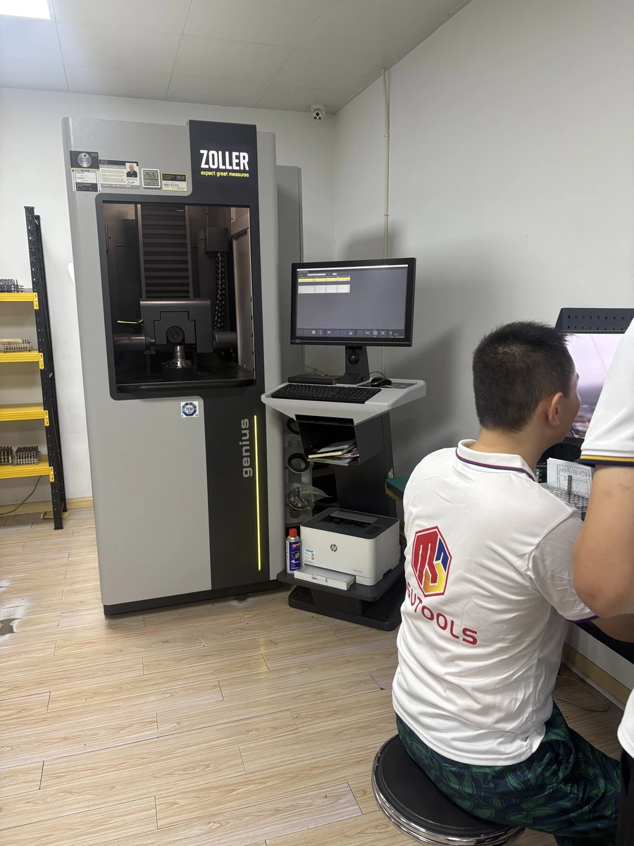
Send the complete tool code and quantity, or email the drawing revision, critical dimensions, material and required surface finish.
MOQ is normally 5–10 pieces, confirmed for the selected product. Samples and sample freight are charged.
Availability, production and shipping timing are confirmed in the quotation. T/T deposit and balance terms are stated with the order.
Include the destination and required packaging. Delivery terms are agreed for the order.
If a tool or dimension is in question, retain the order reference, measurements and photos so the issue can be investigated.
Email Maria at maria@msutools.com or call/WhatsApp +86 13973369578. Send drawings and photos by email.
Confirm the tool reference or drawing revision with quantity and delivery.
View Ordering and DeliveryPCD has bonded diamond grains, while MCD is single-crystal diamond. Keep the specified material and edge geometry when replacing a tool; a similar tool outline does not define the cutting edge.
Typical inquiries include aluminum, copper alloys, graphite, plastics and reinforced materials. Provide the exact composition and operation so grade, edge geometry and tool construction can be selected.
Include the pre-hole diameter, final-hole limits, working length, steps or interruptions, material and holder. State the allowance and the required surface measurement.
Email the part and tool drawings with revision, critical dimensions, tolerances, interface and quantity. Include the workpiece and operating conditions.
Specify the surface roughness or optical requirement and how it will be measured. The diamond material, edge profile, machine, workpiece and cutting conditions must be selected and trialled against that requirement.
Retain the tool and order references, photos of the cutting edge and the machining conditions. Include measured size or surface changes and the point at which the tool was removed.