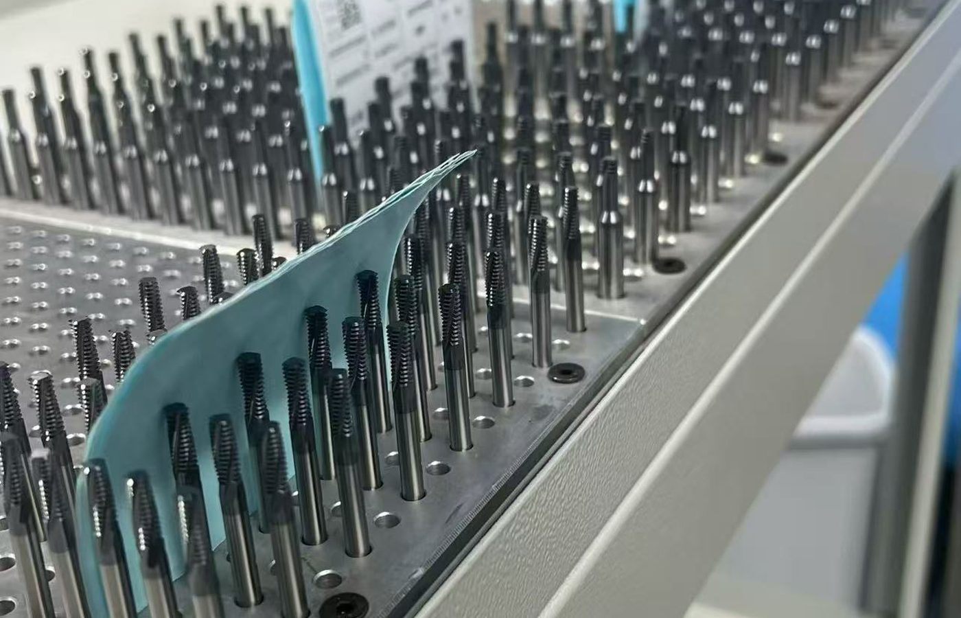
Turning Inserts
For facing, external or internal turning and profiling. Choose a shape that reaches the feature, then match nose radius and chipbreaker to the feed and depth of cut.

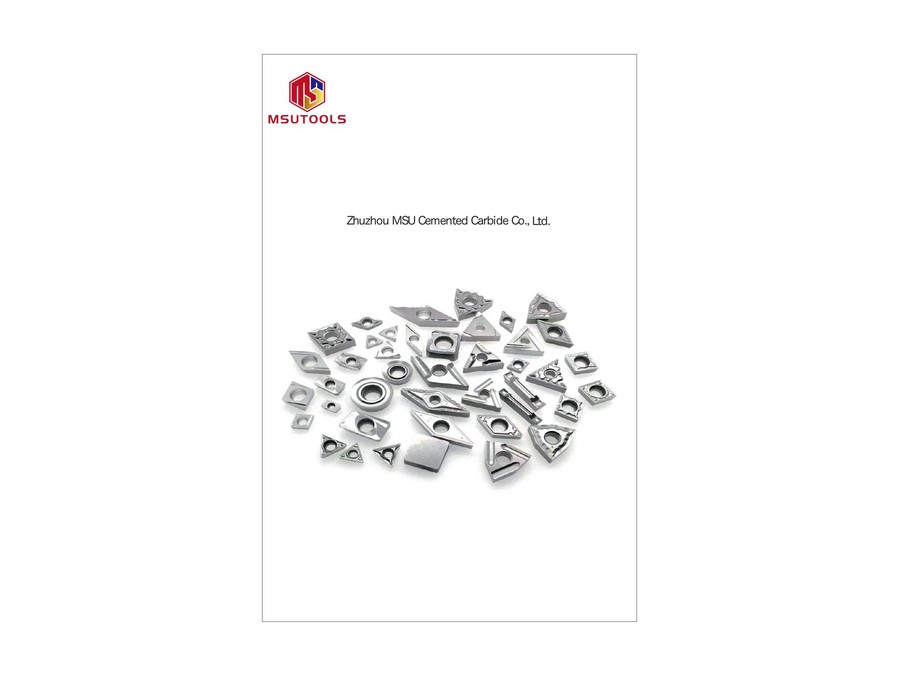
Choose cermet inserts for turning, milling and bearing profiles, or cermet saw tips for blade applications. Match the tool form and dimensions first, then select the grade and cutting edge for the workpiece.
Uncoated and PVD-coated grades include options for steel, stainless steel and cast iron. The material grade, continuity of the cut and finish requirement determine which option to compare.
Send your tool reference and quantity, or describe the cut you need to improve.
Find a Cermet ToolTurning a profile, milling a surface and cutting with a saw use different tool connections and edge geometries. Start with the operation and the tool already installed.
If you are changing cutting material, compare Carbide Inserts and Ceramic Cutting Tools against the same workpiece and cutting conditions.
For facing, external or internal turning and profiling. Choose a shape that reaches the feature, then match nose radius and chipbreaker to the feed and depth of cut.
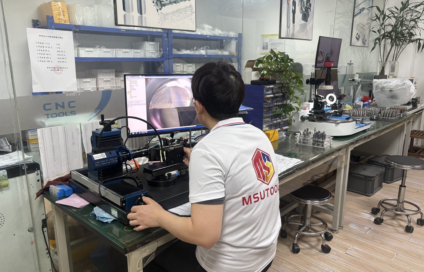
For a matching milling cutter body. Check insert thickness, seat and fastening before comparing grades for the material and cutter engagement.
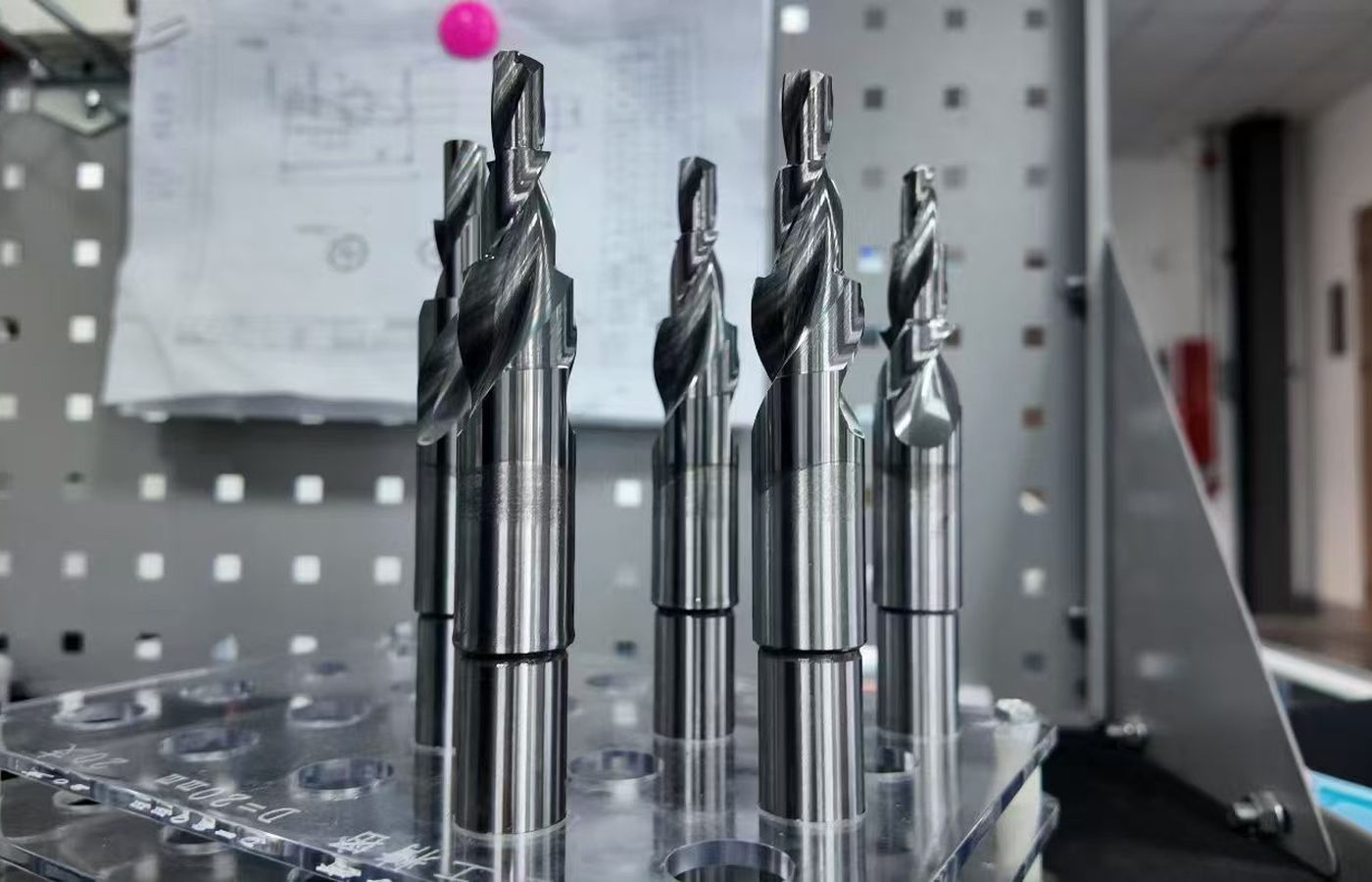
For bearing-component profiles. Use the section drawing to match the cutting profile, width and corner details to the required race or ring feature.
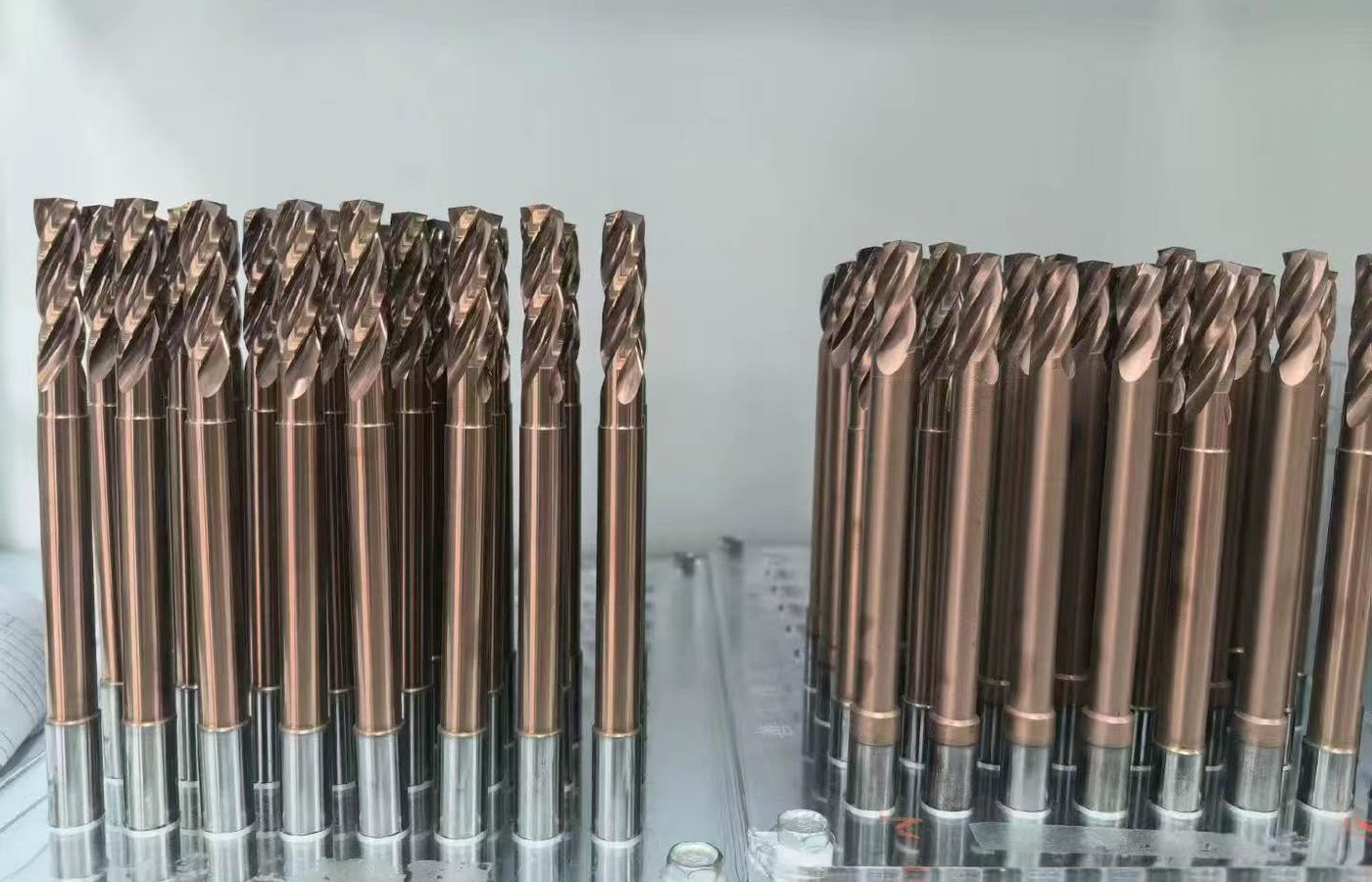
MP99 cermet tips for saw-blade tooth assemblies. Match tip length, width, thickness and profile to the blade design and the material being cut.
Choose the tool form that matches your operation and mounting.
Compare Tool RequirementsThe insert shape sets access and seating. Nose radius, chipbreaker and edge preparation affect how it cuts. Keep these details with the selected cermet grade.
A repeat order needs both the geometry code and grade. When changing the grade or edge, retain the current cutting data so the result can be compared.
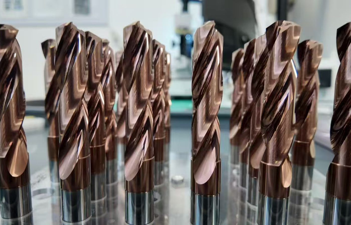
| Tool form | Feature to define | Fit and cutting checks |
|---|---|---|
| Turning insert | Diameter, shoulder or profile | Holder seat, nose radius, chipbreaker, feed and depth of cut. |
| Milling insert | Surface or milled profile | Cutter pocket, fastening, engagement and edge condition. |
| Bearing insert | Race or ring profile | Profile dimensions, corner limits, clamping and material condition. |
| Saw tip | Kerf and tooth profile | Tip dimensions, blade seat, tooth arrangement and cutting material. |
Keep the holder or cutter reference with the insert when checking a replacement.
Check the Cutting SetupFor a replacement, retain the full insert code and grade. For a process change, identify whether the problem is finish, chip control, wear or edge breakage.
For a successful repeat process, keep the geometry and grade unchanged unless the workpiece or cutting conditions have changed.
When comparing Carbide Inserts or Ceramic Cutting Tools, include the current tool life, finished-part measurements and any edge damage.
Email the part drawing, material grade and current cutting conditions.
Discuss a Cermet ApplicationMP20PLUS and MP30 are uncoated. The PVD-coated grades include steel, stainless-steel and cast-iron options. Match a grade to the selected tool geometry before setting cutting conditions.
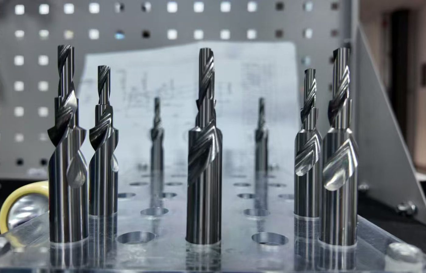
MP20PLUS emphasizes wear resistance in continuous steel cutting. MP30 balances wear resistance and resistance to chipping; compare it when edge damage is part of the problem.
Steel and alloy-steel options for higher-speed, stable cutting. Retain the exact grade designation when matching an existing process.
A steel-cutting option when conditions are less stable. Include interruptions and the current wear pattern when discussing a change from another grade.
A steel-cutting option focused on higher cutting speed and dimensional control. Select cutting data for the actual insert and setup.
PVD-coated grade for stainless-steel finishing in continuous or intermittent cuts. State the alloy grade, hardness and interruption pattern.
PVD-coated grade for cast-iron finishing in continuous or intermittent cuts. Include the casting grade and surface condition.
Use the grade description with the full tool code and dimensional drawing.
View Cermet DimensionsSpecify the tool dimensions and edge features to check. Define finished-part diameter, profile and surface limits separately on the component drawing.
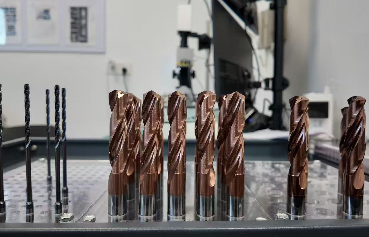
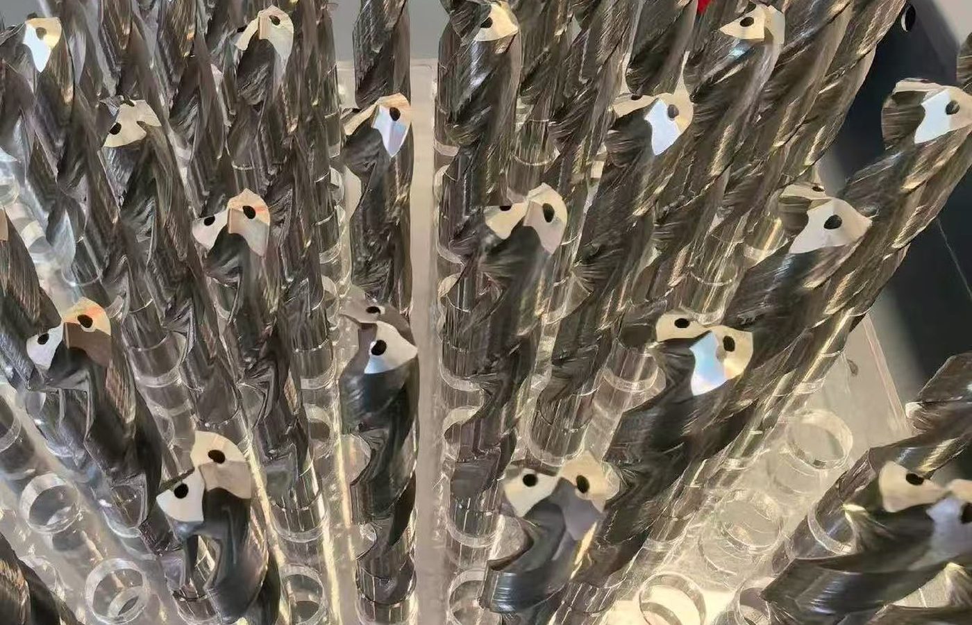
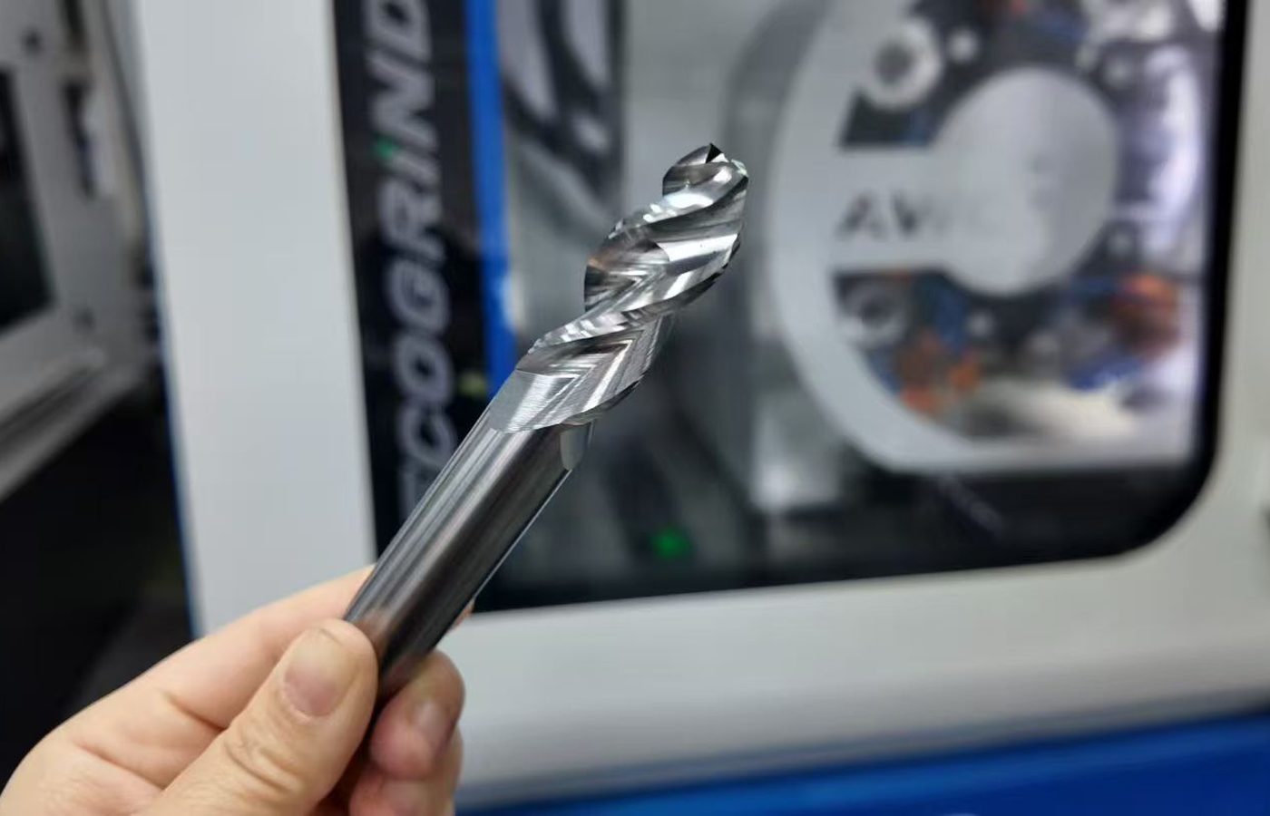
For inserts, specify thickness, seating dimensions, nose radius and edge preparation. For a bearing profile or saw tip, identify the critical profile dimensions on the drawing.
Specify any dimensional report, edge inspection or material identification record needed with the order. Agree the measured features and document scope before ordering.
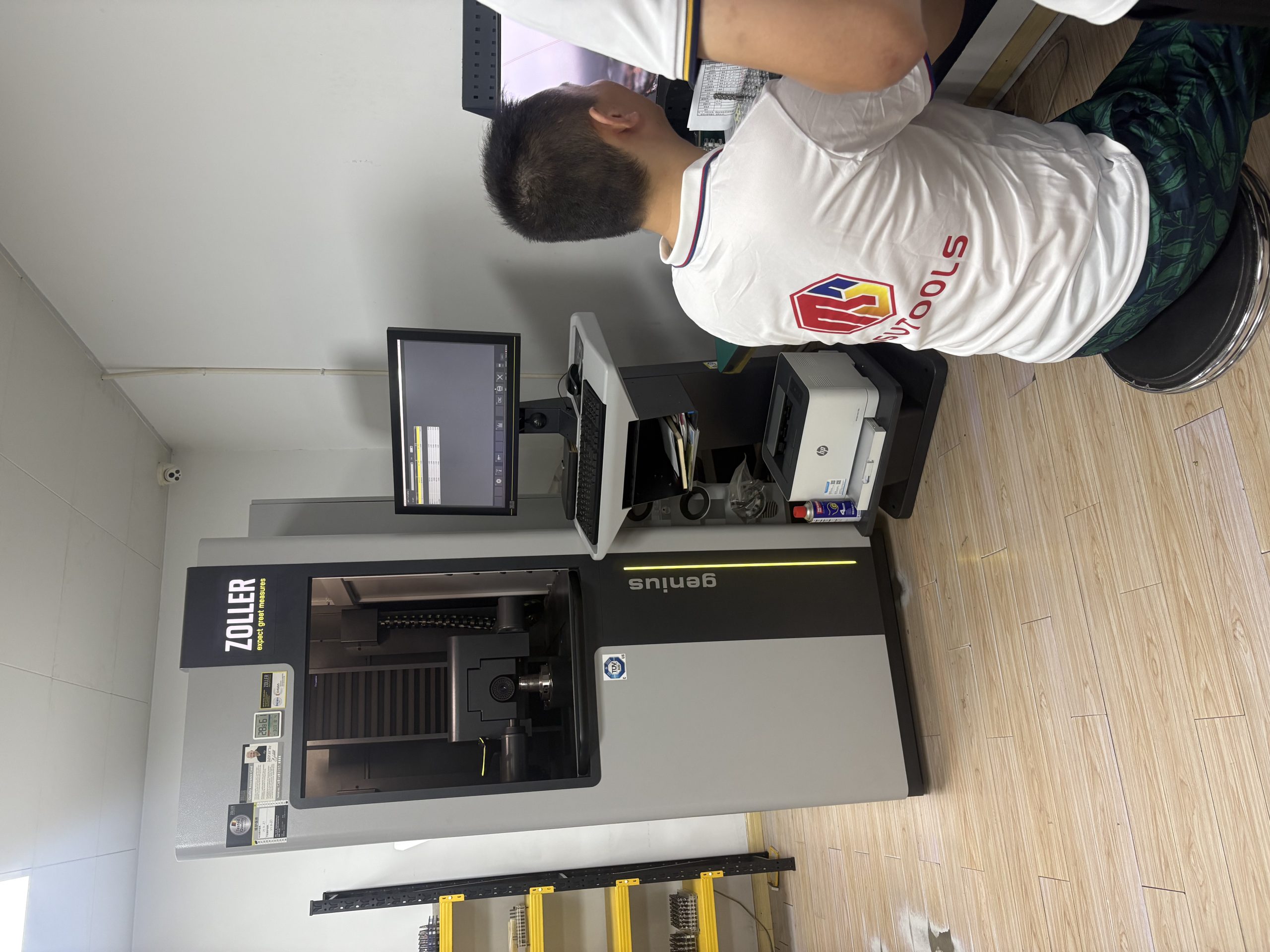
For a machining trial, record the tool reference and cutting conditions with the measured part dimensions and surface finish. See Quality Control for available inspection information.
Identify any measurements or inspection records required with your order.
View Inspection InformationFor a repeat order, send the complete tool reference and quantity. For a new job, email the drawing and describe the feature or machining problem. Ordering and Delivery covers MOQ, payment and shipping. Tool drawings are available in Downloads.
Send the full reference, grade and quantity, or email the part profile with the holder, cutter or blade reference.
MOQ is normally 5–10 pieces, confirmed for the selected product. Samples and sample freight are charged.
Availability, production and shipping timing are confirmed in the quotation. T/T deposit and balance terms are stated with the order.
Include the destination and required packaging. Delivery terms are agreed for the order.
If a tool or dimension is in question, retain the order reference, measurements and photos so the issue can be investigated.
Email Maria at maria@msutools.com or call/WhatsApp +86 13973369578. Send drawings and photos by email.
Check the purchasing terms when confirming the tool, quantity and delivery.
View Ordering and DeliveryUncoated MP20PLUS and MP30 and PVD-coated MP20V, MP30V, MP20HAA and MP20U cover different steel-cutting conditions. Start with continuous or interrupted contact, the current wear pattern and the required finish.
MP20AU is a stainless-steel finishing option; MP20DX is a cast-iron finishing option. Match the actual material, insert geometry and cutting conditions before choosing the grade.
Check the full insert dimensions and clamping arrangement first. Then select the cermet grade, edge geometry and cutting conditions for the job; matching the seat addresses only the mechanical fit.
Record whether damage occurs at entry, at an interruption or after time in cut. Include holder seating, part rigidity, grade, edge preparation and cutting data so those causes can be compared.
Email the component or blade drawing with the required tool profile, critical dimensions, material and quantity. Include the existing tool reference where available.
Send the complete insert code, grade and quantity, or your previous order number. Include any new workpiece material or process change.