

Multi-Form Thread Mills
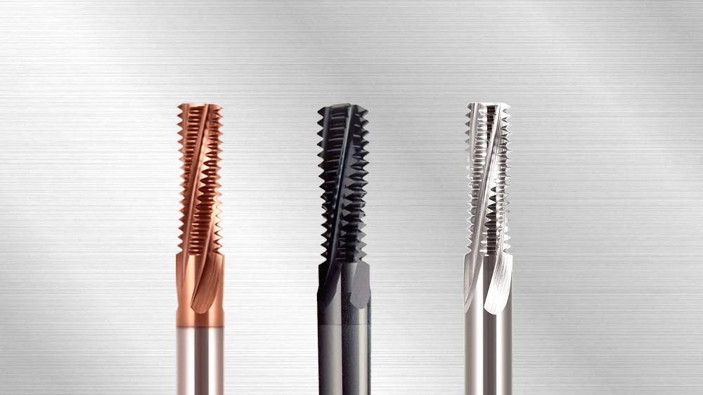
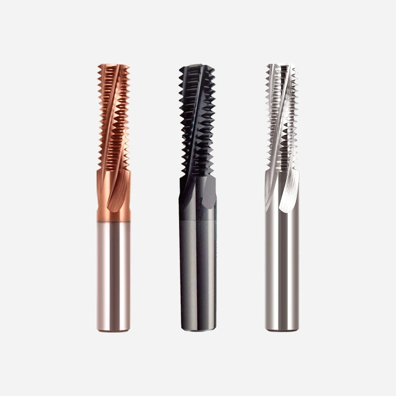
Multi-form thread mills have several thread profiles along the cutting end. MSU offers three-tooth, full-form and two-row designs, with different pitches and working lengths.
Match the tooth arrangement to the required thread length, then check cutting diameter, neck clearance and holder access. The 2D, 3D and 4D options must be checked against the actual dimensions of the part.
Send the full thread callout and usable thread length, or an existing tool reference.
Find a Multi-Form Thread MillCompare the Tooth Arrangements
Three-tooth tools have a short group of axial profiles; full-form tools carry profiles along a longer cutting section. Their pitch and working length must match the thread you need.
Special two-row and tapered designs require their own geometry and machining direction. Select these from the part drawing rather than from an industry name.
-
Three-Tooth Metric Tools
Compare 2D, 3D and 4D length options using the actual L1 and clearance dimensions.
-
Material and Coating Choices
Match the alloy and hardness to the selected geometry and coating specification.
-
Extended and Inch Tools
Compare a longer neck for access or a UNC/UNF profile for the specified inch thread.
-
Full-Form Tools
Match axial tooth pitch and cutting length to the complete Metric or Unified thread requirement.
-
Two-Row and Tapered Tools
Check cutting direction for the two-row design and the part profile for a tapered thread.
Check the pitch, working length and direction for the structure you are considering.
Compare Multi-Form DimensionsMatch Pitch, Length and Clearance
Use the thread dimensions to compare structures. Tooth count and flute count describe different parts of the tool.
| Tool choice | Dimension or condition to check | Selection point |
|---|---|---|
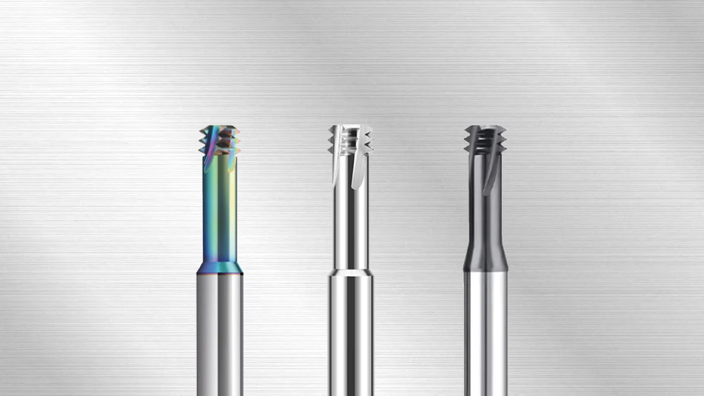
| Three-tooth 2D / 3D / 4D | Actual L1, neck diameter and overall length. | Check access to the full thread and clearance beyond the cutting teeth. |
| Material and coating variants | Workpiece alloy, hardness and the selected coating specification. | A color or application name does not establish the coating chemistry or cutting conditions. |
| Extended Metric / UNC / UNF | Metric pitch or inch TPI, plus working length. | Keep the full thread designation when changing size or reach. |
| Full-form tools | Axial tooth pitch and length of the cutting section. | Match the complete thread profile and required full-thread length. |
| Two-row / tapered tools | Cutting direction, tooth arrangement and part profile. | Use the specific drawing and machining method for the selected design. |
The three-tooth 2D table, for example, lists M6 × 1 with L1 = 12 mm and a 4.8 mm cutting diameter. Read L1 from that tool drawing; it is not the overall length or a blanket allowance for holder clearance.
Compare the tool envelope with the threaded section and the space below it.
Check the Part and Tool FitCheck the Full Thread and Tool Access
Separate the required full-thread length from total hole depth. The cutting end needs clearance to complete its path and withdraw.
- Thread: standard, nominal size, pitch or TPI and tolerance class.
- Length: required full-thread length, hole depth and any unthreaded relief.
- Access: cutting-diameter limit, neck clearance and holder position.
- Direction: internal or external thread and any special tool cutting direction.
- Workpiece and setup: material condition, holder and coolant at the cutting end.
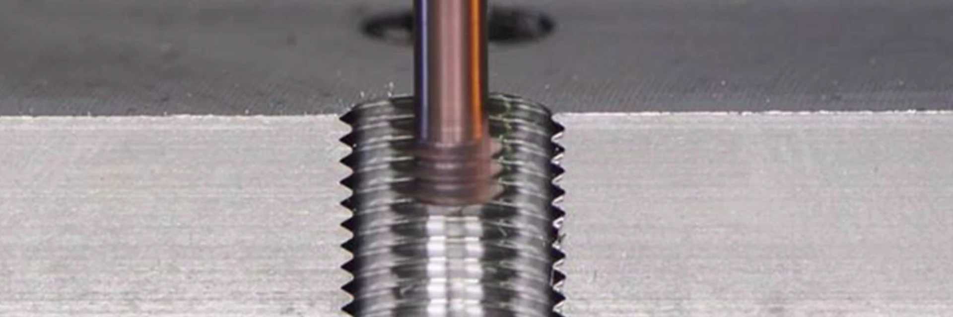
Email the drawing with full-thread length and any bottom-clearance restriction.
Discuss a Multi-Form ToolMulti-Form Options and Working Lengths
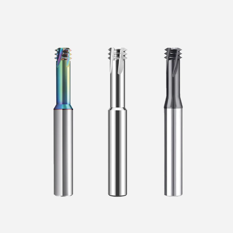
The options below separate tooth arrangement, length and material-specific versions. Check the exact profile and dimensions for each selected tool.
-
Metric Three-Tooth Thread Mills - 2D
Three axial teeth with 2D length options. Check the actual L1 for the selected size.
-
Metric Three-Tooth Thread Mills - 3D
Three axial teeth with 3D length options. Compare neck and holder clearance with the deeper feature.
-
Metric Three-Tooth Thread Mills - 4D
Three axial teeth with 4D length options. Check the full assembly rather than choosing from the length label alone.
-
Titanium / High-Temperature Alloy Three-Tooth Thread Mills - 2D
Three-tooth options for titanium and high-temperature alloys in 2D lengths.
-
Titanium / High-Temperature Alloy Three-Tooth Thread Mills - 3D
Longer 3D options for titanium and high-temperature alloys; select cutting conditions for the alloy and projection.
-
Aerospace-Special Three-Tooth Thread Mills
A special three-tooth design for comparison against the part drawing, material and required documentation.
-
Bronze-Coated Three-Tooth Thread Mills
A bronze-colored coating option; specify the required coating before ordering.
-
DLC Three-Tooth Thread Mills for Non-Ferrous Materials
DLC-coated three-tooth tools for non-ferrous workpieces such as aluminum and copper alloys.
-
Extended Metric Three-Tooth Thread Mills
Longer Metric versions for features requiring additional reach.
-
UNC / UNF Three-Tooth Thread Mills
Three-tooth profiles for UNC or UNF callouts; match the full designation and TPI.
-
Metric ISO Full-Form Thread Mills
Metric ISO profiles along the cutting section; match pitch and full-thread length.
-
UNC / UNF / UNEF Full-Form Range Thread Mills
Inch full-form options covering specified UNC, UNF or UNEF sizes; keep TPI with the size designation.
-
Super-Hard Left-Hand Two-Row Thread Mills
A left-hand-cutting two-row design. Confirm the specified spindle and toolpath direction before use.
-
Taper Medical Bone Plate Thread Mills (55° / 60°)
Tapered profiles with 55° or 60° options for the specified bone-plate drawing. Tool geometry does not establish finished-part certification.
Read length from the model drawing
- Identify the cutting section and any neck or clearance length.
- Match pitch or TPI to the full thread designation.
- Check overall length, shank fit and mounted projection separately.
Use Downloads for the dimension drawings and full size tables.
Check the selected tooth arrangement and working dimensions before ordering.
View Multi-Form DimensionsCheck the Tool and Finished Thread
Agree which tool dimensions need measurement and how the finished thread will be accepted. A tool record and a part-inspection result serve different purposes.
See MSU Factory and Quality Control for equipment and tool-measurement information.
For a trial, record the selected tool, material, mounted projection and program settings alongside the gauge or measurement result. This makes it possible to compare the tool geometry and machining conditions.
Specify the tool dimensions and inspection records required with your order.
View Tool Inspection Information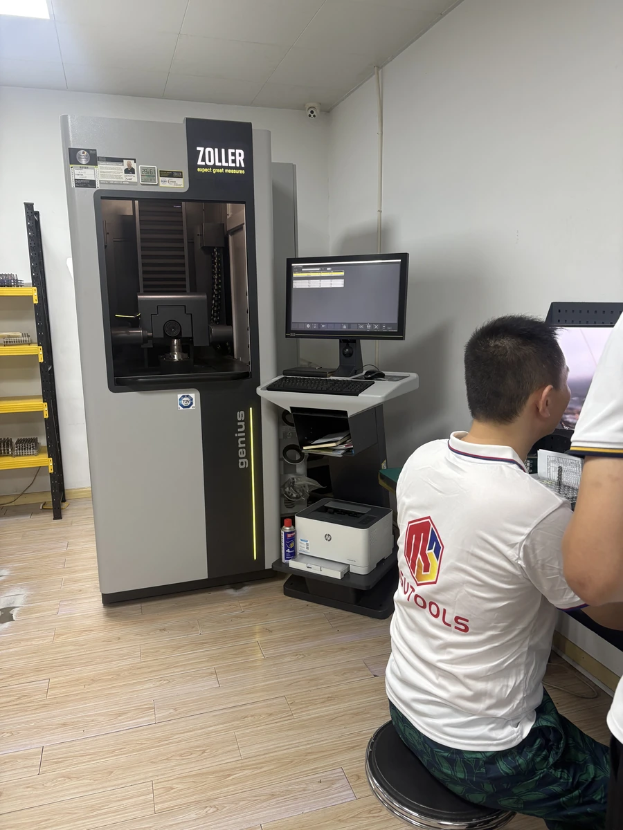
Order a Tool or Discuss a Drawing
The quotation will identify the selected tool, quantity, delivery terms and any agreed inspection records.
Repeat orders
Send the full tool reference or previous order number and quantity. Mention any change to the drawing or workpiece.
New applications
Email the thread and part section with the material. Highlight the dimension or machining problem you need help with.
MOQ and samples
MOQ is normally 5–10 pieces, confirmed for the selected product. Samples and sample freight are charged.
Delivery
Include the destination and required date. Production and shipping timing are confirmed in the quotation.
Payment and quotation
T/T deposit and balance terms, quotation validity and packaging are stated with the quotation or order.
Contact
Email Maria at maria@msutools.com or call/WhatsApp +86 13973369578.
Check the purchasing terms when confirming your tool reference, quantity and delivery.
View Ordering and DeliveryMulti-Form Thread Mills Questions
No. Three-tooth refers to the axial thread profiles. Flute count refers to the cutting edges around the tool and is a separate specification.
A full-form tool has profiles along a longer cutting section; a three-tooth tool has a short group of three axial profiles. Match the pitch and usable cutting length to the required thread.
Use the actual dimensions. For example, the three-tooth 2D M6 × 1 entry lists L1 = 12 mm. Check the tool drawing, full-thread length and bottom clearance before choosing a longer option.
The spacing of its axial profiles is fixed. Match the tool’s specified pitch or TPI to the thread; changing the programmed pitch does not change the spacing of the cutting teeth.
Tool cutting direction and finished-thread hand are separate requirements. Confirm the spindle direction and toolpath for the selected design, and specify the thread hand on the drawing.
No. Specify the required material, dimensions, inspection and documentation for the application. Any approval must be supported by the relevant records.
Keep the tool reference, thread callout, gauge or measurement result, material and program settings together. Include the tool projection and a photo of the cutting edges when reporting wear or finish problems.