
Combination Drill & Thread Mills
Combination drill and thread mills produce the hole and thread with one integrated tool. MSU offers designs that mill the bottom hole and designs with a drill point; chamfering is included on specified versions.
Choose by the operations your part needs, then match hole depth, usable thread length and tool clearance. The steel bottom-hole/thread version and the drill/chamfer/thread versions do not perform the same set of operations.
Email the hole and thread drawing, including any chamfer, or send an existing tool reference.
Find a Combination ToolChoose the Hole-Making and Threading Method
These tools differ in how they create the hole. Compare the bottom-hole milling designs with the drill-point designs before choosing the size.
The non-ferrous bottom-hole design includes a chamfering feature. The steel bottom-hole/thread design specifies hole and thread milling; a chamfering operation must be checked separately.
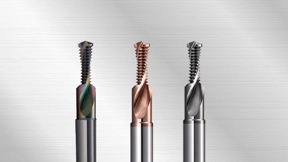
Bottom-Hole / Thread / Chamfer Combination Mills for Non-Ferrous Materials
Mills the bottom hole and thread, with chamfering, for non-ferrous workpieces.
Compare the cutter diameter and working length with the complete hole and thread section.
Bottom-Hole / Thread Combination Mills for Steel
Mills the bottom hole and thread for steel workpieces.
Check steel grade, hardness and coolant delivery; chamfering is not stated for this version.
Drill / Chamfer / Thread Combination Mills
Uses a drill point for the hole and includes chamfering and internal thread milling.
Match both the drill diameter and the thread size. Leave space for the drill point beyond the required thread.
DLC Drill / Chamfer / Thread Combination Mills
DLC-coated drill-point design with chamfering and internal thread milling.
Match the non-ferrous alloy and check the drill, thread and chamfer dimensions together.
Check which operations are included before comparing tool lengths.
Compare the Included OperationsCheck the Operations Included
The hole-making method determines which dimensions and machining motions must be checked. Choose the tool and program together for the actual feature.
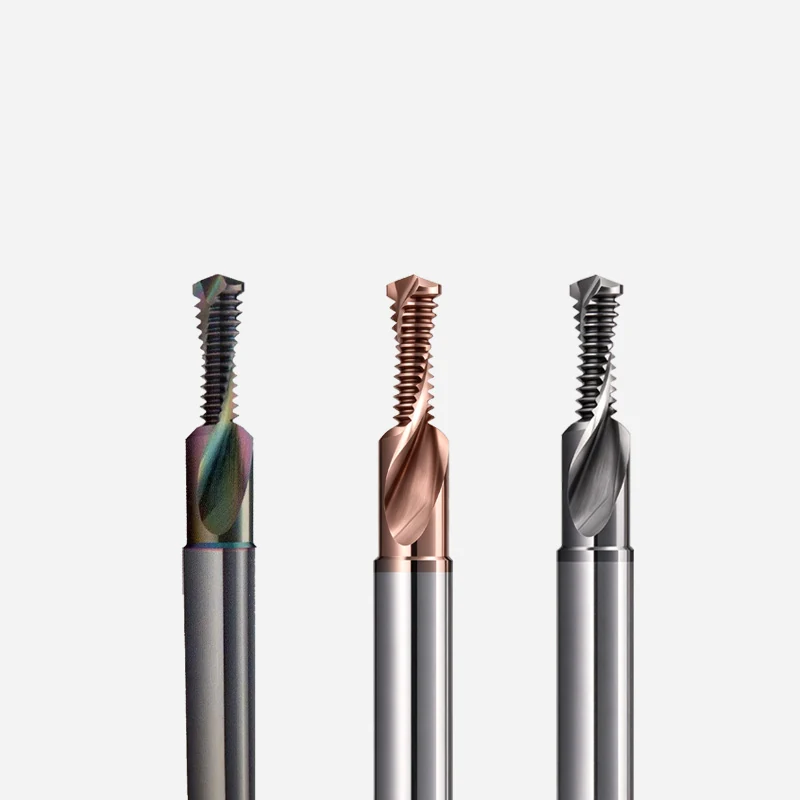
| Tool design | Included operations | Feature to check |
|---|---|---|
| Non-ferrous bottom-hole / thread / chamfer | Hole milling, thread milling and chamfering. | Hole diameter, full-thread depth, entry chamfer and available clearance. |
| Steel bottom-hole / thread | Hole milling and thread milling. | Steel condition, bottom clearance and the model’s coolant arrangement; check chamfering separately. |
| Drill / chamfer / thread | Drilling, chamfering and internal thread milling. | Drill diameter and point allowance, thread dimensions and chamfer position. |
| DLC drill / chamfer / thread | Drilling, chamfering and internal thread milling with DLC coating. | The same combined dimensions, matched to the non-ferrous workpiece. |
The bottom-hole milling versions are described for use without a separate pre-drilling operation. Their milling motion differs from the drill-point versions. Confirm the program for the selected tool, machine and stock condition; do not transfer a sequence between the two designs.
Check the finished hole, thread and chamfer on the same section drawing.
Match Hole and Thread DimensionsMatch the Hole, Thread and Chamfer
For a blind hole, total depth must accommodate the tool end as well as the usable thread. On a drill-point tool, check the point allowance separately.
- Thread: full designation, pitch and required usable thread length.
- Hole: finished or existing bore, total depth and blind or through condition.
- Chamfer: required angle, diameter or width, and position at the entry.
- Clearance: room for the tool end, neck and holder through the intended motion.
- Material and machine: alloy, hardness, control and coolant delivery.
Email the section drawing with hole depth, full-thread length and chamfer dimensions.
Discuss a Combination ToolCompare M6 × 1 Tool Dimensions
These M6 × 1 examples show why thread size alone cannot identify a combination tool. All dimensions below are in mm; use the selected model drawing for final selection.
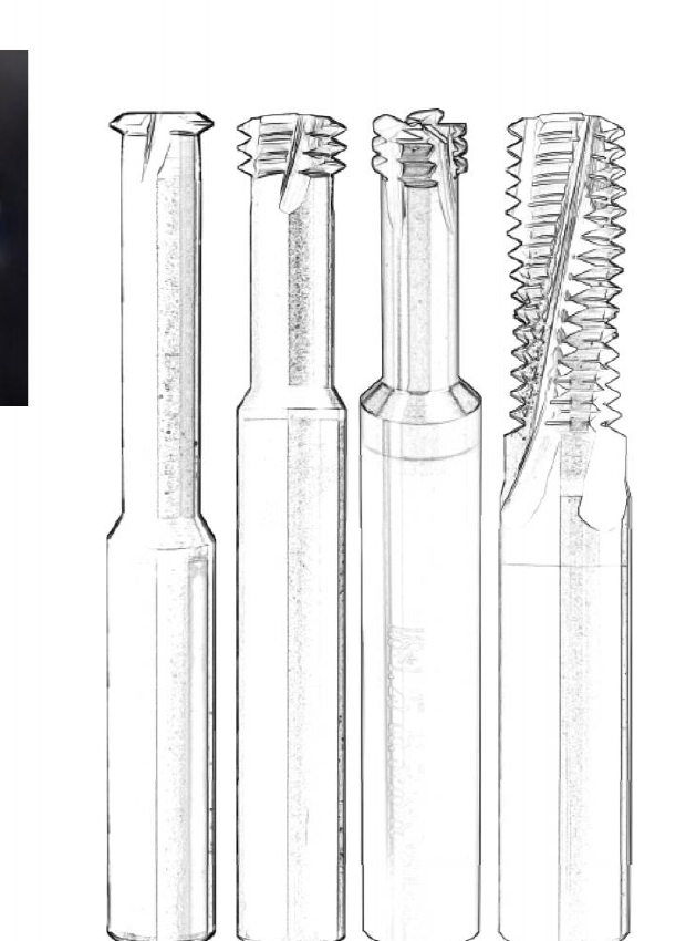
Bottom-Hole / Thread / Chamfer Combination Mills for Non-Ferrous Materials
M6 × 1 bottom-hole / thread / chamfer example
Cutting diameter d1 4.7; working length L1 14; shank D 6; overall length L 50; 3 flutes.
Bottom-Hole / Thread Combination Mills for Steel
M6 × 1 steel bottom-hole / thread example
Cutting diameter d1 4.7; working length L1 14; shank D 6; overall length L 50; 4 flutes. This listed size uses external cooling.
Drill / Chamfer / Thread Combination Mills
M6 × 1 drill / chamfer / thread example
Drill diameter d1 5.0; thread-cutting diameter d2 4.8; L1 12; drill-point length L2 1.0; shank D 8; overall length L 60; 2 flutes.
DLC Drill / Chamfer / Thread Combination Mills
M6 × 1 DLC drill / chamfer / thread example
Drill diameter d1 5.0; thread-cutting diameter d2 4.8; L1 12; drill-point length L2 1.0; shank D 8; overall length L 60; 2 flutes.
Read symbols on the selected drawing
- d1 identifies the cutter diameter on the bottom-hole milling designs and the drill diameter on the drill-point designs.
- L1 and L2 identify different tool features; neither should be substituted for the required full-thread depth.
- Check shank fit and mounted reach separately from the overall length.
Match the workpiece and coating specification before ordering. These dimensions identify examples; they do not specify a machining program or cutting conditions.
Use Downloads for the complete dimension drawings and other sizes.
Check all combined features on the drawing for the selected size.
View Combination Tool DimensionsInspect the Hole, Thread and Chamfer
A combined tool produces several features. Identify how hole size, full-thread length and the chamfer will each be measured.
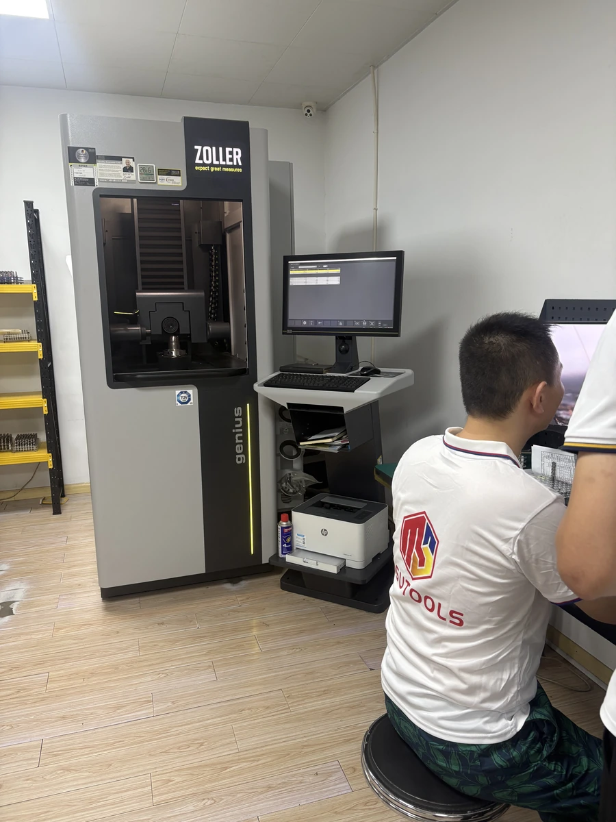
See MSU Factory and Quality Control for equipment and tool-measurement information.
Keep results for the hole, thread and chamfer separate when reporting a problem. Include the tool reference and program sequence so a dimensional issue can be traced to the relevant operation.
Specify the tool dimensions and inspection records required with your order.
View Tool Inspection Information
Order a Tool or Discuss a Drawing
The quotation will identify the selected tool, quantity, delivery terms and any agreed inspection records.
Repeat orders
Send the full tool reference or previous order number and quantity. Mention any change to the drawing or workpiece.
New applications
Email the thread and part section with the material. Highlight the dimension or machining problem you need help with.
MOQ and samples
MOQ is normally 5–10 pieces, confirmed for the selected product. Samples and sample freight are charged.
Delivery
Include the destination and required date. Production and shipping timing are confirmed in the quotation.
Payment and quotation
T/T deposit and balance terms, quotation validity and packaging are stated with the quotation or order.
Contact
Email Maria at maria@msutools.com or call/WhatsApp +86 13973369578.
Check the purchasing terms when confirming your tool reference, quantity and delivery.
View Ordering and DeliveryCombination Drill & Thread Mills Questions
No. The non-ferrous bottom-hole design and both drill-point designs specify chamfering. The steel bottom-hole/thread design specifies hole and thread milling, so check any required chamfer separately.
The bottom-hole milling versions are described for use without separate pre-drilling. The drill-point versions include drilling. Confirm the chosen tool’s motion and dimensions against the actual stock and hole condition.
No. The bottom-hole milling designs use an interpolated milling motion; the drill-point designs have a drilling operation. Use the program for the selected design rather than transferring one sequence to all tools.
The cutting geometry differs. In the examples above, the bottom-hole milling cutter has d1 = 4.7 mm, while the drill-point version has a 5.0 mm drill diameter and a separate 4.8 mm thread-cutting diameter.
They describe different requirements. A blind hole needs clearance for the tool end, including any drill point. Use the part section and selected tool drawing to establish the required allowance.
No. The listed M6 example uses external cooling, while some larger sizes specify internal cooling. Check the coolant arrangement for the exact size and the machine connection.
Email the section drawing with the full thread callout, hole depth, required chamfer and material. Include the machine and coolant arrangement so the proposed tool can be checked against the complete operation.