
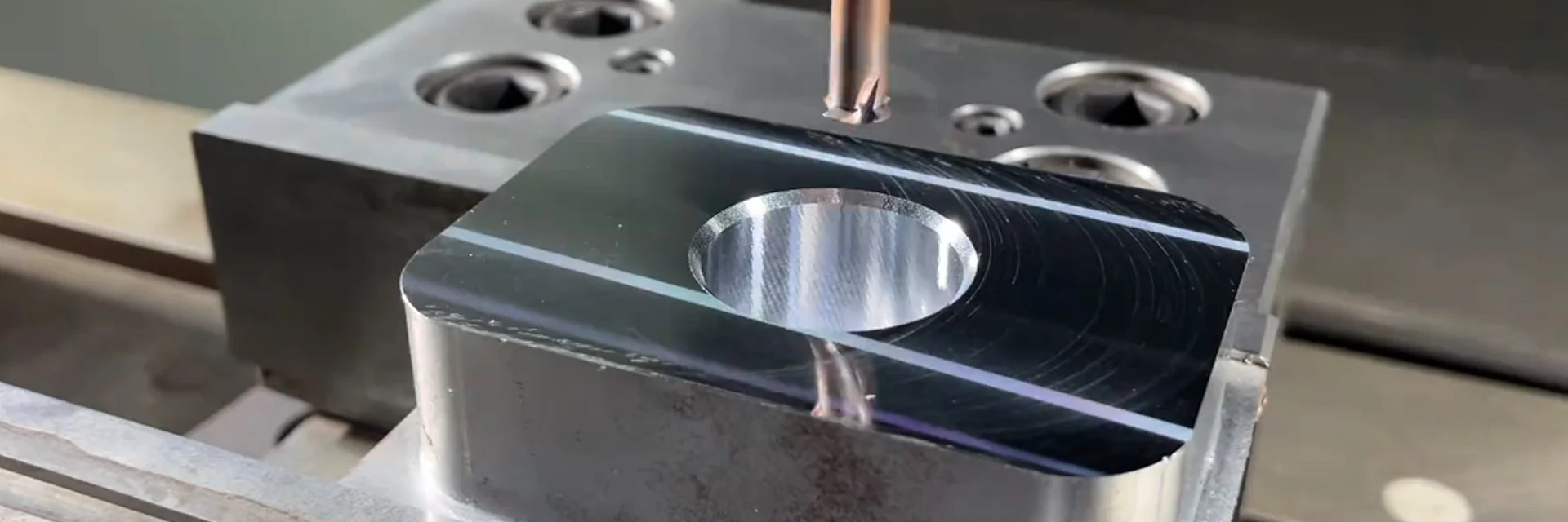
Single-Form Thread Mills
Single-form thread mills have one axial thread profile at the cutting end. Also called single point or single tooth thread mills, they form the thread as the tool follows a programmed helical path.
MSU offers 60° and 55° profiles, trapezoidal, ACME and PG options, plus extended-reach and pitch-range designs. Choose the profile and permitted pitch first, then check neck clearance and working length.
Send the thread callout and depth, or your existing tool reference for a quote.
Find a Single-Form Thread MillChoose the Profile and Pitch Range
The thread form determines the cutting profile. A pitch-range tool can cover only the range stated for that size; an extended tool changes access, not the thread standard.
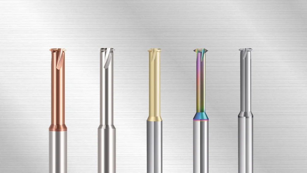
Match material and coating to the actual workpiece grade and condition. The available choices include steel, titanium/high-temperature-alloy and DLC options for non-ferrous workpieces.
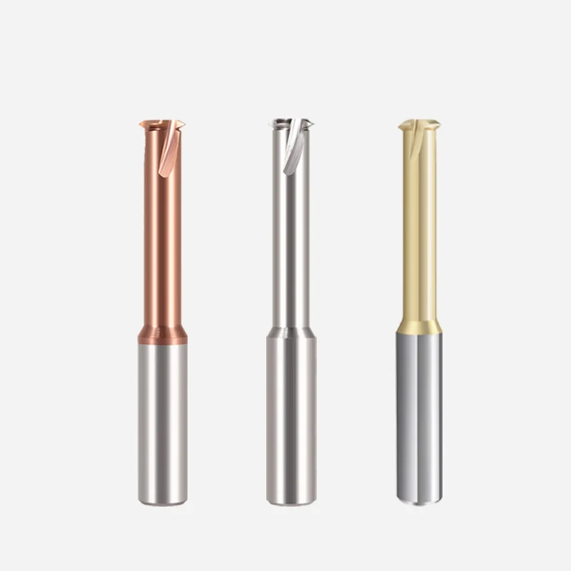
60° Profiles and Reach
Choose the required size and pitch, then check whether the standard or extended neck clears the feature.
- 60° cutting profile
- Standard or extended reach
- Material-specific options
Pitch-Range Tools
Compare the stated pitch interval with your threads. Two tools with the same profile angle can have different pitch limits.
- Stated minimum and maximum pitch
- Cutting and neck diameters
- Neck length for the required depth
Other Thread Forms
Match the full standard as well as the angle. A 55° inch, trapezoidal, ACME or PG requirement needs its corresponding profile.
- 55° inch profiles
- 30° trapezoidal and 29° ACME
- PG thread forms
Compare the permitted pitch with the space around the threaded feature.
Compare Single-Form DimensionsCheck Pitch and Working Dimensions
These checks distinguish the thread the tool can form from the depth it can reach.
| Selection point | What to match | Why it matters |
|---|---|---|
| Profile and pitch | Full thread designation; stated pitch or TPI interval for the selected tool. | A matching angle alone does not establish the correct thread form. |
| Cutting and neck diameters | Cutting diameter d1 and clearance diameter d2 on the tool drawing. | The cutter must enter the feature and the neck must clear it through the path. |
| Working and overall lengths | L1, shank D and overall length L on the selected drawing. | A longer overall tool is not automatically usable at the full length. |
A steel pitch-range example lists 0.5–1.5 mm pitch, d1 = 4.8 mm, d2 = 2.9 mm and L1 = 15 mm. Each of those limits must suit the job; the pitch range alone is not enough to select it.
Use the part section to check the usable thread length and bottom clearance.
Check Thread Depth and AccessMatch the Tool to the Part Drawing
For a callout such as M6 × 1, retain the tolerance class and required full-thread depth from the drawing. Check the internal or external form before selecting the tool.
- Thread: full designation, tolerance class and right- or left-hand requirement.
- Depth: usable thread length and the hole or shoulder position beyond it.
- Clearance: entry opening, neck space and holder access.
- Material: exact grade, hardness and condition for the intended cut.
- Setup: machine, holder and coolant arrangement when selecting a new tool.
Email the thread detail and part section when you need help choosing the working length.
Discuss a Single-Form ToolSingle-Form Options and Dimensions
Compare the available profiles and length options below. Use the full dimensional drawing to select the exact tool.
-
General 60° Single-Form Thread Mills
60° single-form geometry for a specified size and pitch.
-
Titanium / High-Temperature Alloy Single-Form Thread Mills
Single-form options for titanium and high-temperature alloys; match the grade and machining conditions.
-
Extended-Reach 60° Single-Form Thread Mills
Extended-neck 60° geometry. An M6 × 1 example has d1 4.8 mm, d2 3.4 mm, L1 15 mm, shank 6 mm and overall length 100 mm.
-
Pitch-Range Single-Form Thread Mills for Steel
60° tools with a stated pitch interval for each cutting diameter, including the 0.5–1.5 mm example above.
-
Extended Pitch-Range Single-Form Thread Mills
Pitch-range geometry with longer neck options where the feature needs extra clearance.
-
Pitch-Range Single-Form Thread Mills for Titanium / High-Temperature Alloy
Pitch-range options for titanium and high-temperature alloys; the permitted pitches remain specific to each size.
-
DLC Pitch-Range Single-Form Thread Mills for Non-Ferrous Materials
DLC-coated pitch-range options for non-ferrous workpieces such as aluminum and copper alloys.
-
55° Inch Pitch-Range Single-Form Thread Mills
55° inch profiles with TPI coverage specified by tool size.
-
30° Trapezoidal Single-Form Thread Mills
30° trapezoidal profiles; match the metric pitch and complete thread designation.
-
29° ACME Single-Form Thread Mills
29° ACME profiles; match the designation and TPI.
-
PG German Standard Single-Form Thread Mills
PG profiles for the specified PG thread size. Use the PG drawing rather than selecting a 55° or 60° tool.
Read the selected tool drawing
- Match d1 and d2 to cutting and neck clearance.
- Check L1, shank D and overall length L separately.
- Keep the specified pitch or TPI with the complete tool reference.
Find the full dimension tables in Downloads.
Check the selected profile, pitch interval and tool dimensions before ordering.
View Single-Form DimensionsSpecify the Thread Inspection Requirements
Keep the required thread profile, tolerance class and usable length with the part drawing. Specify any tool measurement records needed before ordering.
See MSU Factory and Quality Control for equipment and tool-measurement information.
If a trial thread does not meet the drawing, retain the tool reference, workpiece condition, program settings and inspection result. Include the mounted projection when asking about wear or finish.
Specify the tool dimensions and inspection records required with your order.
View Tool Inspection Information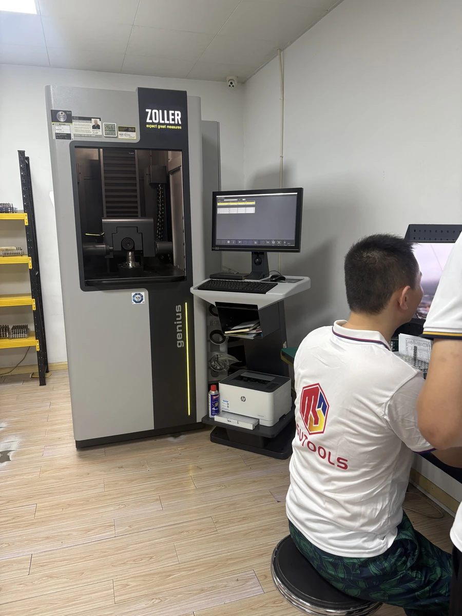
Order a Tool or Discuss a Drawing
The quotation will identify the selected tool, quantity, delivery terms and any agreed inspection records.
Repeat orders
Send the full tool reference or previous order number and quantity. Mention any change to the drawing or workpiece.
New applications
Email the thread and part section with the material. Highlight the dimension or machining problem you need help with.
MOQ and samples
MOQ is normally 5–10 pieces, confirmed for the selected product. Samples and sample freight are charged.
Delivery
Include the destination and required date. Production and shipping timing are confirmed in the quotation.
Payment and quotation
T/T deposit and balance terms, quotation validity and packaging are stated with the quotation or order.
Contact
Email Maria at maria@msutools.com or call/WhatsApp +86 13973369578.
Check the purchasing terms when confirming your tool reference, quantity and delivery.
View Ordering and DeliverySingle-Form Thread Mills Questions
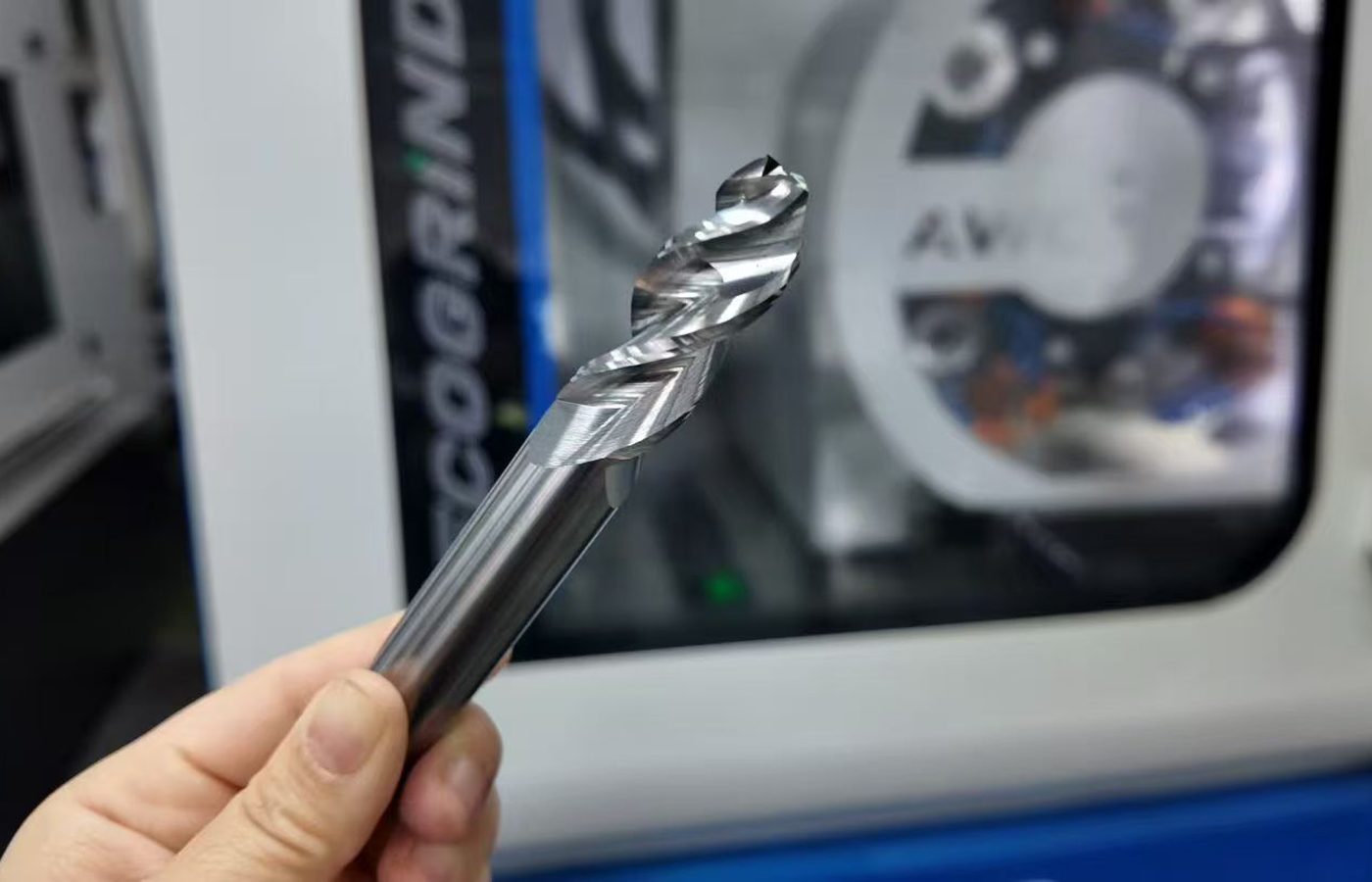
No. Single-form describes one axial thread profile. Flute count describes the cutting edges around the tool; check both on the selected model drawing.
No. Some tools specify one size and pitch; pitch-range tools state an interval for each size. Stay within that interval and also check the required thread profile and diameter.
Use the full standard and designation. A 60° angle does not distinguish Metric from Unified threads, and ACME, trapezoidal and PG threads require their own profiles.
Not necessarily. Neck length, neck diameter, clamping length and holder clearance determine access. Compare those dimensions with the full thread depth and the space beyond it.
Confirm the profile and intended path for the selected tool. State internal or external on the drawing; the single-form name alone does not establish suitability for both.
Use the exact alloy, hardness and condition with the proposed tool geometry. A broad material label is only a starting point, especially when changing from steel to titanium or a non-ferrous alloy.
Send the complete tool reference or dimension drawing and the required quantity. Include the existing thread callout if you want to compare a different profile or working length.