
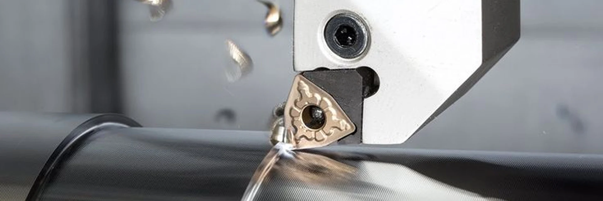
Shallow Hole Drilling Inserts
Find SPMG and WCMX carbide shallow hole drilling inserts for a specified drill body. Start with the full body and insert references, including the pocket position being replaced.
Match seating dimensions and clamping before choosing geometry and grade for the hole. The drill assembly determines the usable hole diameter and depth.
Send the drill-body code, insert reference and pocket position for a replacement quote.
Find a Drilling InsertMatch the Insert to the Drill Pocket
SPMG and WCMX have different shapes and seating dimensions. Use the body’s specified insert designation to identify the replacement.
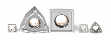
Keep the insert position with the full body reference when comparing replacements.
Compare Drilling Insert FitSeparate Insert Fit from Hole Capacity
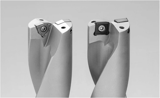
Insert dimensions describe the replaceable cutting component. Hole capacity comes from the matched body, cutting components and assembled setup.
Do not assign SPMG or WCMX to a center or peripheral pocket from the family name alone. Follow the specified insert arrangement for the exact drill body.
| Selection factor | What to identify | What it establishes |
|---|---|---|
| Drill body | Manufacturer and complete model | The specified insert sizes and assembly requirements. |
| Insert family | SPMG or WCMX with the full code | The insert form and dimensional variant. |
| Seating dimensions | Thickness, seat and mounting-hole geometry | Fit in the designated pocket. |
| Clamping | Correct screw or fastening arrangement | How the insert is secured in the body. |
| Insert position | Pocket assignment from the body instructions | Which replacement is needed in a multi-insert drill. |
| Geometry and grade | Full suffix and selected grade | The cutting edge being supplied for that position. |
| Hole size and depth | Finished diameter and full-diameter depth | The required capacity of the complete drill. |
| Entry and exit | Flat, inclined or interrupted surfaces | How the cutting edges enter and leave the material. |
| Material and coolant | Actual grade, hardness and supply method | The context for selecting cutting conditions. |
Check the drill assembly and hole section before changing an insert specification.
Check the Drilling SetupIdentify the Pocket and Hole Conditions
When replacing a damaged edge, record its position before removal. A photo of the drill tip and the insert pockets helps identify which component failed.
- Existing componentsRecord the drill-body model and all insert markings, including suffix and grade.
- Pocket positionIdentify the pocket being replaced and photograph the seating and fastening parts.
- Hole requirementShow finished diameter, depth, blind bottom or breakthrough, and tolerance.
- Entry and exitInclude inclined faces, cross-holes or interruptions shown on the part section.
- Material and coolantState material grade and hardness with the coolant delivery method.
- Current processRecord speed, feed, chip condition and where wear or breakage appears.
Email a drill-tip photo and hole section when the failed insert or position is unclear.
Discuss a Drilling InsertCompare SPMG and WCMX Dimensions
The examples below identify one size in each family. They show insert dimensions, not a drilling-diameter range. All dimensions are in millimeters.
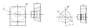
SPMG
SPMG050204-DG
L 5, IC 5, S 2.38, d 2.2, Re 0.4. Match this complete size to the specified body pocket.
WCMX
WCMX030208-U
L 3, IC 5.56, S 2.38, d 2.8, Re 0.8. Check the seating and fastening arrangement for this size.
Read the drilling-insert drawing
- L and IC: dimensions of the insert shape
- S: insert thickness
- d: mounting-hole dimension
- Re: corner radius
- Geometry suffix and selected grade
- Body reference and pocket assignment
Find the full size tables in Downloads. Match every seating dimension and the specified insert position before replacing a component.
Use the dimension drawing and full designation to identify the insert you need.
View Insert DimensionsInspect the Insert and Finished Hole
Agree any insert dimensional checks required with the order. Define finished-hole diameter, depth and surface acceptance separately for the drilling trial.
See MSU Factory and Quality Control for equipment and tool-measurement information.
For a hole-size problem, record where along the hole the measurements were taken. Keep the body code and insert positions with the cutting data and used-edge photos.
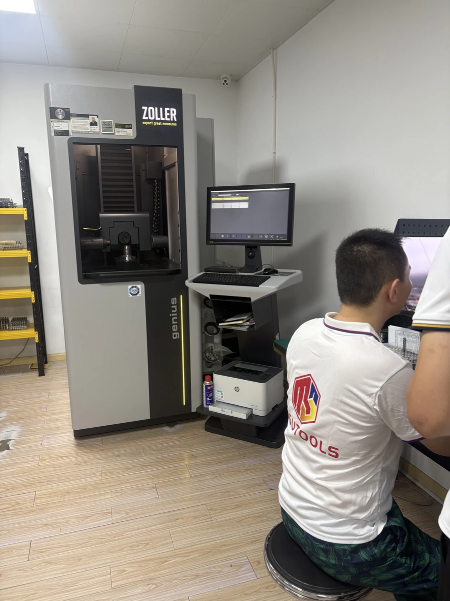
State any insert measurements and inspection records required before ordering.
View Inspection InformationOrder a Replacement or Discuss a Drawing
For a repeat order, use the full insert reference and grade. For a new application, email the drawing and identify the machining problem or feature that needs attention.
Repeat orders
Send the complete insert designation, geometry suffix, grade and quantity, or your previous order number.
New applications
Include the body code, pocket position, hole drawing, material and coolant method. Email drawings to Maria using the address below.
MOQ and samples
MOQ is normally 5–10 pieces, confirmed for the selected product. Samples and sample freight are charged.
Delivery and payment
Availability, production and shipping timing are confirmed in the quotation. T/T deposit and balance terms are stated with the order.
Purchasing information
Ordering and Delivery covers purchasing terms; Downloads provides insert drawings.
Contact
Email Maria at maria@msutools.com or call/WhatsApp +86 13973369578.
Review the purchasing terms when confirming the selected insert, quantity and delivery.
View Ordering and DeliveryShallow Hole Drilling Inserts Questions
Answers to common fit, selection and replacement questions.
These families have different shapes and seating dimensions. Use the insert specified for the exact drill body and pocket; they are not interchangeable by family name.
Use the insert arrangement in the drill-body instructions. The SPMG or WCMX family name does not identify the center or peripheral position on every drilling system.
No. The body geometry and assembled cutting components establish drilling diameter. Match the complete body reference to the required hole.
The quotation lists the inserts and quantities supplied. For a different tool construction, compare Holemaking Tools, including Replaceable Head Drills.
Follow the body’s specified insert and grade arrangement for the material. Include each pocket position when asking about a grade change.
Keep photos of the failed edge, drill tip, pocket and chips. Include the body and insert references, material, hole depth, coolant and cutting conditions, and note when the failure occurred.
Send the full insert designation, geometry suffix, grade, pocket position and quantity, or the previous order number. Retain the body reference if any component changes.