
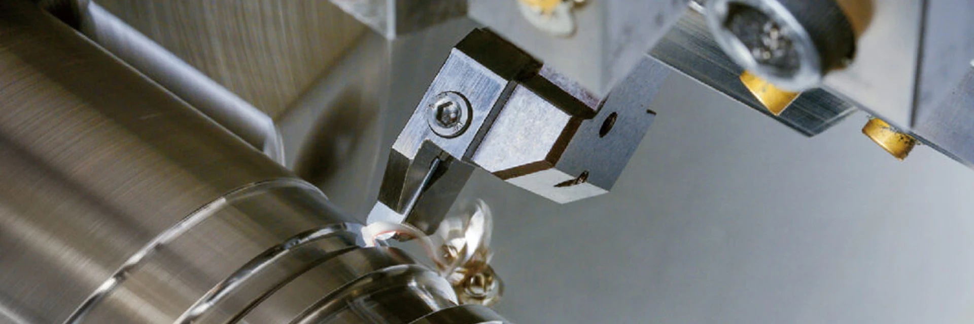
Grooving and Parting Inserts
Choose MGMN carbide grooving and parting inserts in 2, 2.5, 3, 4 and 5 mm cutting widths. Match the width and corner radius to the groove or cut-off requirement.
Then check the selected insert with the holder or blade. Groove depth, cut-off diameter and clearance around the workpiece determine the reach the assembled tool needs.
Send the groove drawing or cut-off diameter with your insert and holder references.
Find a Grooving or Parting InsertChoose for a Groove or a Cut-Off
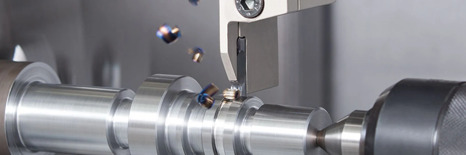
A groove has a finished width, depth and corner requirement. A cut-off also needs enough reach to separate the part without the holder contacting the workpiece.
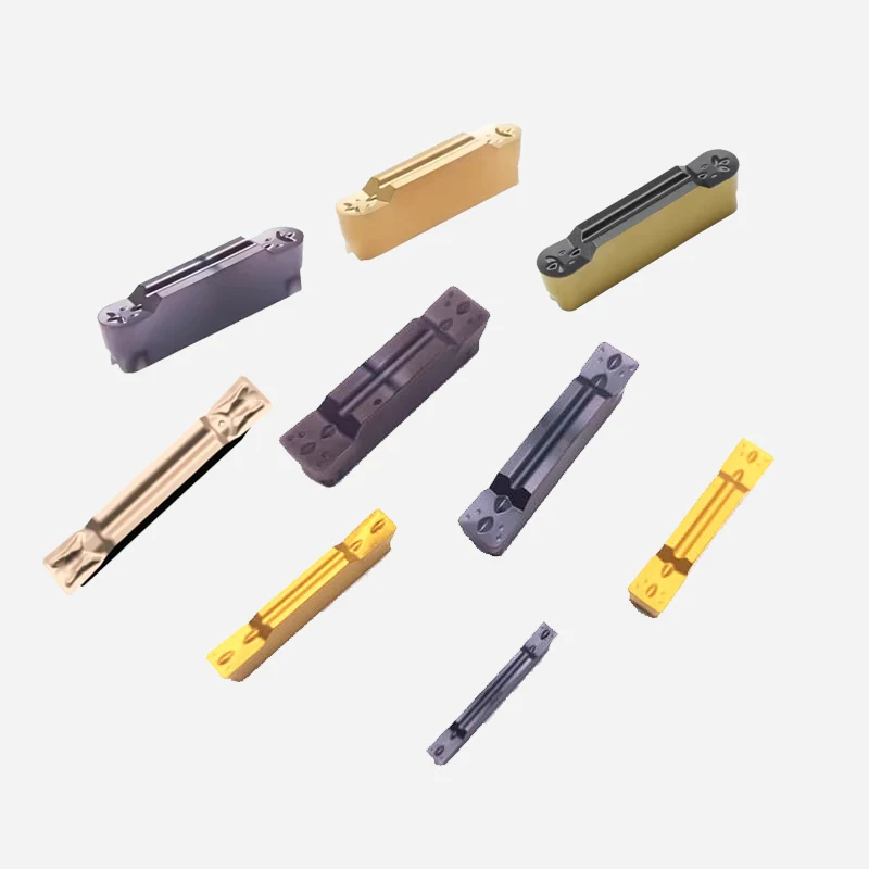
Cutting widths from 2 to 5 mm
MGMN200-GM, MGMN250-GM, MGMN300-GM, MGMN400-GM and MGMN500-GM offer distinct width and body dimensions. Match the selected size to its holder seat.
Grooving
Use the finished groove width and bottom-corner requirement to choose the cutting edge. Show the groove location and depth on a part section.
Parting / cut-off
Use the bar or tube dimensions to check required reach. Compare cutting width with material loss and the stability of the holder or blade.
Separate the finished feature dimensions from the reach and support of the tool.
Compare Grooving RequirementsMatch Width, Radius and Working Reach
The insert dimensions define the cutting edge and seating geometry. Maximum groove depth and cut-off capacity depend on the complete holder or blade assembly.
| Selection factor | For a groove | For a cut-off |
|---|---|---|
| Cutting width | Match the groove width and machining strategy. | Compare kerf width with material loss and tool stability. |
| Corner radius | Check the bottom-corner limits on the drawing. | Check the edge and remaining feature after separation. |
| Depth or diameter | Use the radial groove depth and surrounding clearance. | State the outside diameter and bore diameter for a tube. |
| Holder or blade | Check reach without rubbing the groove walls. | Check reach to the required separation point. |
| Seating and clamping | Match insert size and seat geometry. | Match insert size and seat geometry. |
| Tool position | Set alignment and center height for the operation. | Check alignment and center height before the cut. |
| Chip clearance | Allow chips to leave a confined groove. | Check chip flow through the developing cut. |
| Material and grade | Use actual material grade and hardness. | Include solid bar or tube condition and interruptions. |
| Coolant and cutting data | Match delivery and feed to the groove. | Use cutting guidance for the selected tool assembly. |
Check the part section and tool assembly before choosing additional reach.
Check the Grooving SetupCheck Clearance Along the Whole Cut
Keep holder projection as short as the feature allows. For a deep groove or a large cut-off diameter, check the supported length and coolant access at full reach.
- Groove drawingShow width limits, radial depth, corner radius and distance to nearby shoulders.
- Cut-off dimensionsState bar diameter, or tube outside and inside diameters, plus the required cut width.
- Tool assemblyIdentify the holder or blade and its permitted depth for that insert size.
- AlignmentCheck center height, clamping and the approach to the workpiece.
- Material and chipsInclude material grade, coolant delivery and any chip packing in the cut.
- Current problemRecord where burrs, chatter, edge breakage or width variation appear.
Email the part section and holder reference to discuss the required reach.
Discuss a Grooving or Cut-Off JobCompare MGMN Widths and Dimensions
The five GM-designation examples below have different widths, thicknesses and corner radii. All dimensions are in millimeters.
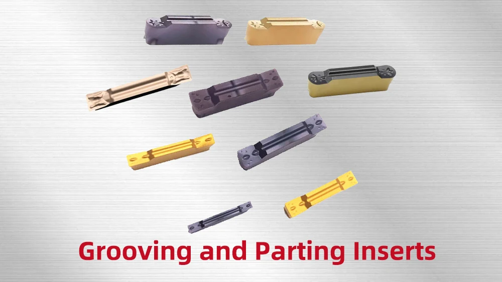
MGMN-GM size options
MGMN200-GM: W 2, L 18, S 3.55, Re 0.2. MGMN250-GM: W 2.5, L 18.5, S 3.57, Re 0.2. MGMN300-GM: W 3, L 21, S 4.83, Re 0.4. MGMN400-GM: W 4, L 21, S 4.88, Re 0.3. MGMN500-GM: W 5, L 26, S 5.8, Re 0.4.
Read the MGMN dimension drawing
- W: cutting width
- L: insert length
- S: insert thickness
- Re: corner radius
- Matching holder seat and permitted reach
The Downloads catalog shows the MGMN drawing and grade options. Insert length is not the tool’s maximum grooving depth; check that capacity with the holder.
Use the dimension drawing and full designation to identify the insert you need.
View Insert DimensionsMeasure Groove Width and Corner Requirements
Define finished-groove width, depth and bottom-corner limits on the part drawing. State any insert-width or radius measurement records required with the order.
See MSU Factory and Quality Control for equipment and tool-measurement information.
For width variation, keep measurements along the groove with the insert code, holder projection and cutting conditions. For a cut-off problem, retain the burr or remaining-pip measurements.
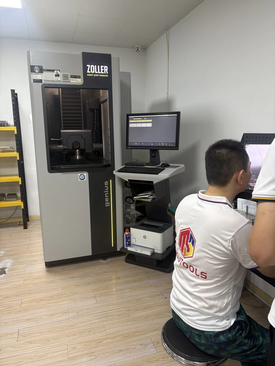
State any insert measurements and inspection records required before ordering.
View Inspection InformationOrder a Replacement or Discuss a Drawing
For a repeat order, use the full insert reference and grade. For a new application, email the drawing and identify the machining problem or feature that needs attention.
Repeat orders
Send the complete insert designation, geometry suffix, grade and quantity, or your previous order number.
New applications
Show groove width, depth and corner limits, or the cut-off diameter and holder reference. Email drawings to Maria using the address below.
MOQ and samples
MOQ is normally 5–10 pieces, confirmed for the selected product. Samples and sample freight are charged.
Delivery and payment
Availability, production and shipping timing are confirmed in the quotation. T/T deposit and balance terms are stated with the order.
Purchasing information
Ordering and Delivery covers purchasing terms; Downloads provides insert drawings.
Contact
Email Maria at maria@msutools.com or call/WhatsApp +86 13973369578.
Review the purchasing terms when confirming the selected insert, quantity and delivery.
View Ordering and DeliveryGrooving and Parting Inserts Questions
Answers to common fit, selection and replacement questions.
The listed GM-designation inserts have widths of 2, 2.5, 3, 4 and 5 mm. The complete codes and corner radii are shown in the dimensions section.
The nominal width identifies the cutting edge. Finished-groove acceptance follows the part drawing and measurement after machining; alignment, tool deflection and the cutting strategy also affect the result.
Use the required radial depth and compare it with the selected holder or blade’s permitted reach. The MGMN insert length alone does not define depth capacity.
Check the holder’s specified insert size and seat. The examples differ in length and thickness as well as width, so they should not be assumed interchangeable.
Send the part section and exact holder reference. Internal and face grooves need suitable access and holder geometry; the MGMN family name alone does not establish that capability.
Record the cut-off diameter, holder projection, alignment, material and cutting data. Include photos of the failed edge and chips, and note where in the cut the failure occurred.
Send the full MGMN code, grade and quantity, or the previous order number. Keep the holder reference when changing size or replacing an unfamiliar insert.