
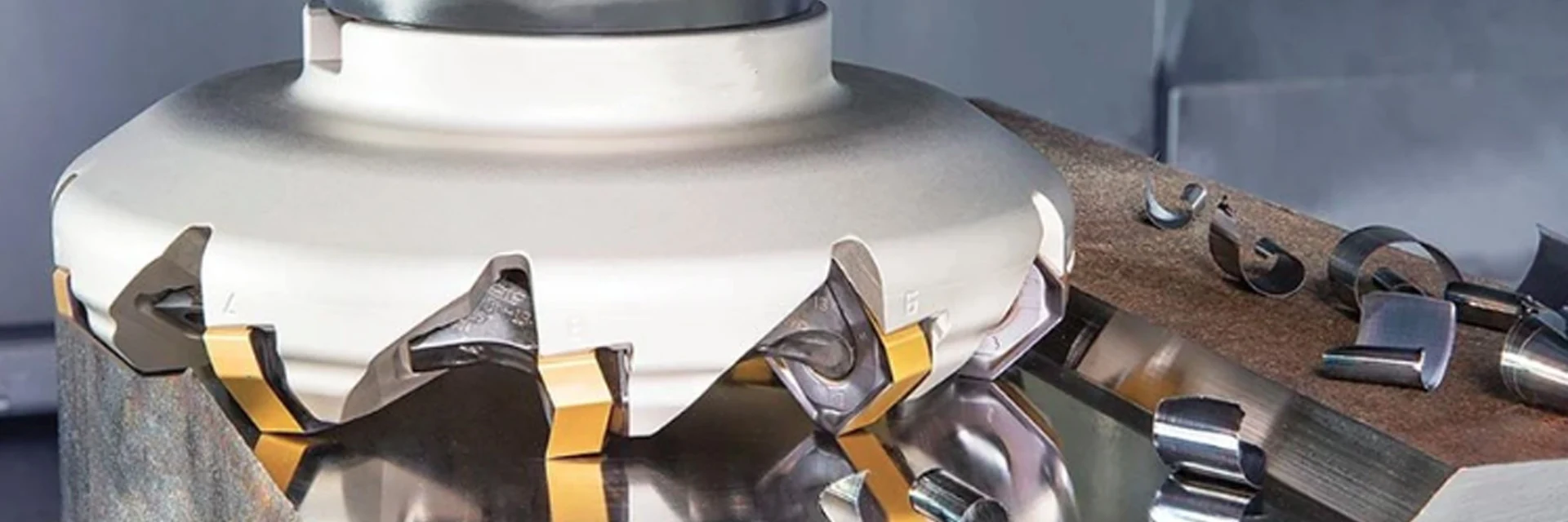
Milling Tool Holders
Milling tool holders connect your cutting tool to the machine spindle. Choose from milling chuck arbors, shell mill arbors, end mill adapters, power milling chucks and HSK holders.
Start with the connection at each end, then check the projection length and clearance around the workpiece. The holder, cutting tool and required accessories need to fit as one assembly.
Have a holder code? Send it with the quantity. Need help choosing? Tell us your spindle interface and cutting tool.
Find a Milling HolderMatch the Spindle and Tool Connections
Choose the holder around the cutter connection, then match its machine interface. A spindle designation alone does not identify the tool-side connection.
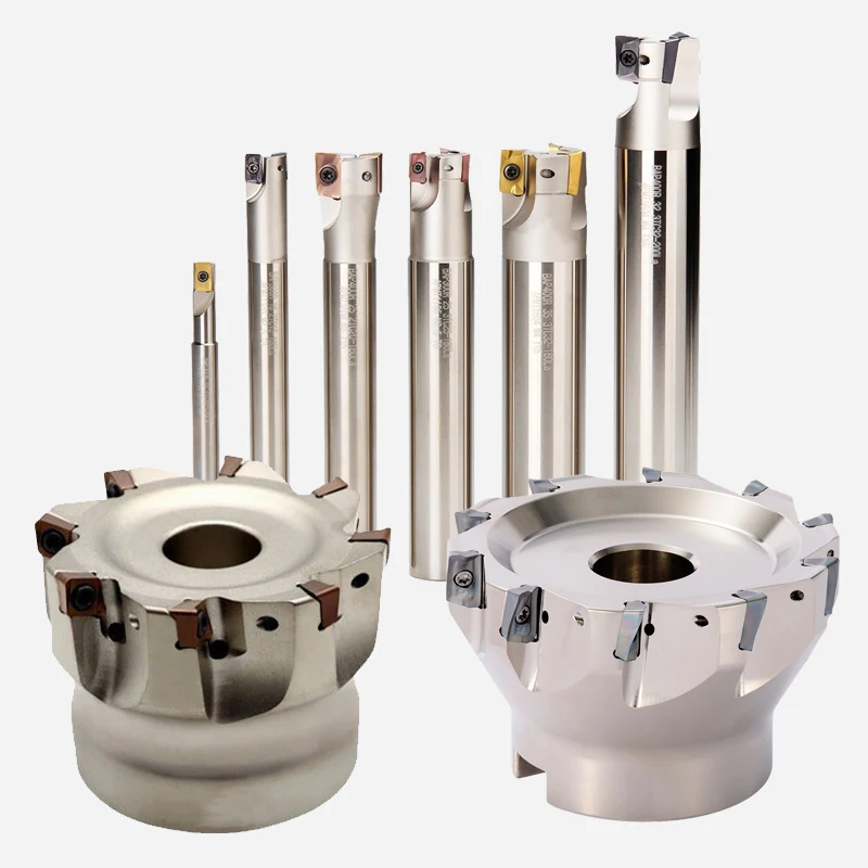
| Holder type | Tool connection | Dimensions to match | Assembly check |
|---|---|---|---|
| Milling chuck arbors | Milling chuck connection | Spindle interface, chuck connection and projection | Match the chuck and any separate clamping components |
| Shell mill arbors | Shell mill bore and drive | Pilot diameter, drive arrangement and projection | Check the retaining screw and cutter mounting dimensions |
| End mill adapters | Straight tool shank | Bore, shank diameter and projection | Match the tool shank and retention detail |
| Power milling chucks | Chuck clamping system | Clamping size, spindle interface and projection | Confirm the specified clamping components and accessories |
| HSK holders | Selected toolholding system | Complete HSK form and size, tool connection and projection | Check retention and coolant requirements for the machine |
Match the cutter and holder
A shell mill needs a matching mounting bore and drive arrangement; a straight-shank end mill needs the appropriate bore or clamping system.
Next, check whether the assembled holder and tool can reach the feature with sufficient clearance.
Check Reach and ClearanceCheck Reach, Coolant and Accessories
After matching the connections, check the holder and cutting tool against the workpiece and fixture.
- Working reachdistance from the holder reference position to the feature being machined.
- Clearancespace around the chuck, cutting tool, workpiece and fixture.
- Coolantmachine supply and the required route through or around the tool.
- Operating requirementsspindle speed, runout measuring position and any specified balance requirement.
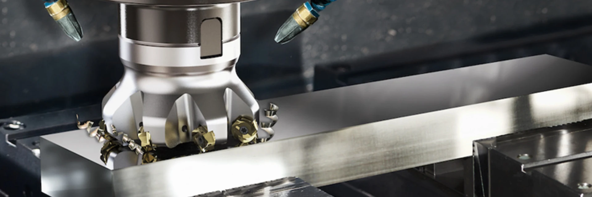
Reach the feature
Measure the usable projection from the machine reference position, including the cutting tool. Check clearance through the full machining path.
Avoid unnecessary overhang
Keep overhang as short as the feature and fixture allow. If a longer assembly is needed, include the required reach and operating conditions with the enquiry.
Complete the assembly
Confirm the coolant path and required pull stud, nut, collet or spanner. These components should be identified separately in the quotation.
Send a setup sketch if access or projection is the main constraint.
Discuss Your SetupFind the Right Holder Drawing
A full holder code is the quickest way to find its drawing. A spindle designation alone leaves the tool-side connection and projection unspecified.
For an unreadable marking, a drawing or photo of both ends and the projection helps identify the replacement. Check the cutter mounting details on the same drawing.
Find dimensional drawings and component references in Downloads.
Use the full model reference to find the corresponding drawing and components.
Find Drawings and ComponentsDimensions and Inspection Requirements
Specify runout and balance with the conditions under which they will be checked.
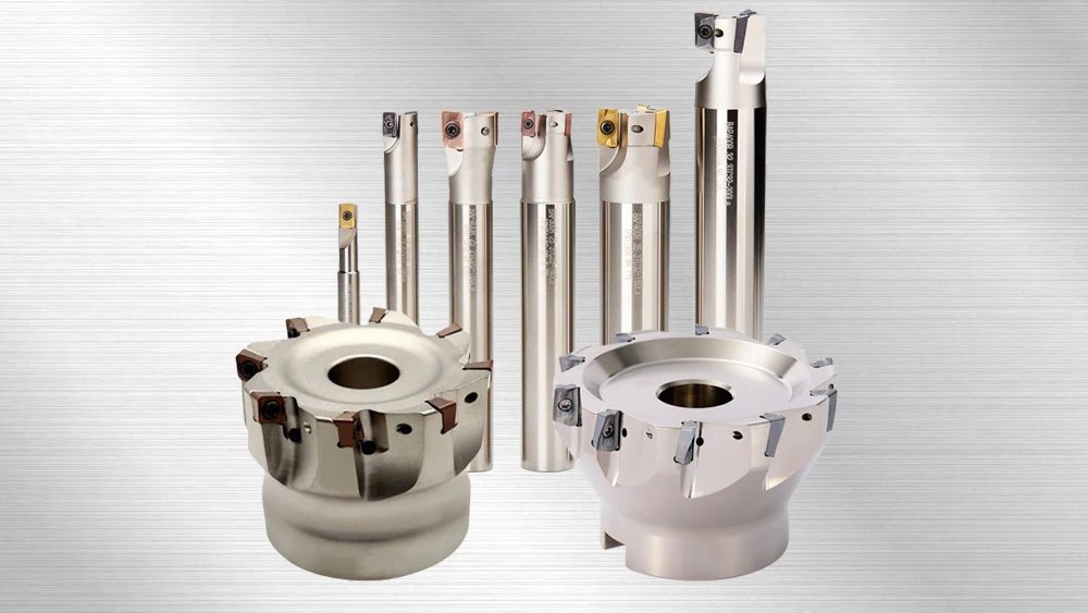
For runout, identify the holder, test bar and measuring position. For balance, state the required grade and operating speed. A value without its test conditions is insufficient to compare assemblies.
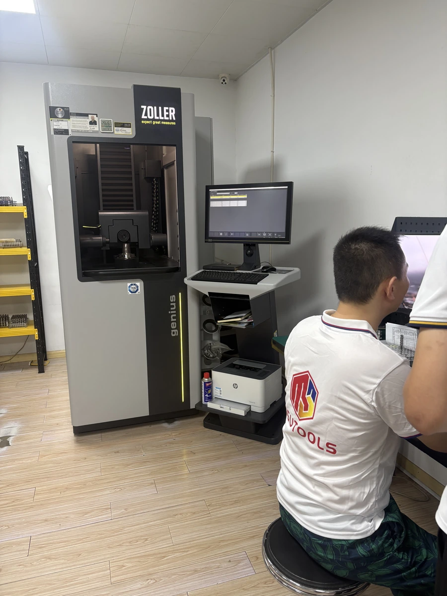
Request any dimensional report or material document before ordering. The quotation identifies the available records and inspection scope.
Need inspection records? Include the measured features and test conditions in your enquiry.
View Quality ControlRequest a Quote
For a repeat order, send the full model and quantity. For help choosing, email the part detail or current setup to Maria.
MOQ and samples
MOQ is normally 5–10 pieces, confirmed by quotation. Samples are charged; sample freight is paid by the customer.
Lead time
Your quotation confirms production timing. Shipping time is stated separately.
Contact
Maria: maria@msutools.com · +86 13973369578 (phone or WhatsApp). Email drawings and photos.
Your quotation sets the payment, delivery and packaging terms for the order.
View Ordering InformationMilling Holder Questions
No. The machine connection and cutting-tool connection are separate. The full holder reference also identifies the selected size and projection.
The quotation identifies the included items. Accessories should be listed individually when you need them supplied with the holder.
Yes, identification can start from a drawing or photos of both connections and the projection. Include the cutting-tool connection so the replacement can be matched at both ends.
No. The assembled cutter and holder must clear the workpiece and fixture throughout the machining path. Overall holder length alone does not establish that clearance.